 PCB
PCB FPC
FPC Rigid-Flex
 FR-4
FR-4 HDI PCB
 Rogers High-Frequency Board
 PTFE Teflon High-Frequency Board
 Aluminum
 Copper Core
 PCB Assembly
 LED light PCBA
 Memory PCBA
 Power Supply PCBA
 New Energey PCBA
 Communication PCBA
 Industrial Control PCBA
 Medical Equipment PCBA
 Testing Service
 PCBA Testing Service
 Certification Application
 RoHS Certification Application
 REACH Certification Application
 CE Certification Application
 FCC Certification Application
 CQC Certification Application
 UL Certification Application
 Transformers, Inductors
 High Frequency Transformers
 Low Frequency Transformers
 High Power Transformers
 Conversion Transformers
 Sealed Transformers
 Ring Transformers
 Inductors
 Wires,Cables Customized
 Network Cables
 Power Cords
 Antenna Cables
 Coaxial Cables
 Net Position Indicator
 Solar AIS net position indicator
 Capacitors
 Connectors
 Diodes
 Embedded Processors & Controllers
 Digital Signal Processors (DSP/DSC)
 Microcontrollers (MCU/MPU/SOC)
 Programmable Logic Device(CPLD/FPGA)
 Communication Modules/IoT
 Resistors
 Through Hole Resistors
 Resistor Networks, Arrays
 Potentiometers,Variable Resistors
 Aluminum Case,Porcelain Tube Resistance
 Current Sense Resistors,Shunt Resistors
 Switches
 Transistors
 Power Modules
 Isolated Power Modules
 AC-DC Power Modules
 DC-AC Module(Inverter)
 RF and Wireless
Professional Analysis of Laser Drilling Parameter Optimization for Ceramic Substrates
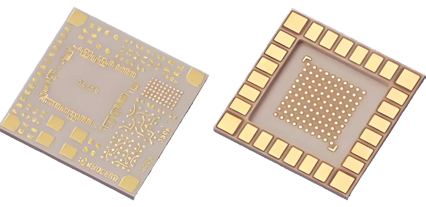
Professional Analysis of Laser Drilling Parameter Optimization for Ceramic Substrates
CeramIC substrates (e.g., Al₂O₃, AlN) pose challenges in laser drilling, including crack formation, heat-affected zone (HAZ) expansion, and hole geometry control, due to their high hardness, high melting point, and low thermal expansion coefficient (CTE). Parameter optimization must address laser characteristics, material response, and process stability, focusing on the following key aspects:
I. Laser Type and Wavelength Selection
-
UV Laser (355nm)
-
Advantages: High photon energy (~3.5eV) breaks ceramic bonds, minimizing thermal diffusion; ideal for high-reflectivity ceramics (e.g., AlN).
-
Applications: Micro-vias (≤100μm) with HAZ ≤20μm.
-
-
CO₂ Laser (10.6μm)
-
Advantages: High average power (>100W) for thick substrates (>1mm) but with significant HAZ.
-
Applications: Coarse holes (>200μm) with lower precision requirements.
-
II. Core Parameter Optimization Strategies
1. Energy Parameters
-
Pulse Energy:
-
Low Energy (<0.1mJ): Reduces HAZ but requires multiple pulses (10–20) for penetration.
-
High Energy (>1mJ): Single-pulse penetration for thick substrates but risks microcracks.
-
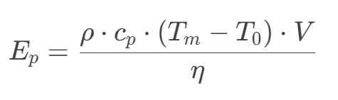
Optimization Formula:
-
: Density, : Specific heat, : Melting point, : Ablated volume, : Absorption rate.
-
-
Pulse Width:
-
Ultrafast (ps/fs): Cold ablation mechanism (HAZ ≤5μm), high equipment cost.
-
Nanosecond (10–100ns): Balances cost and quality, requires thermal management.
-
2. Temporal-Spatial Parameters
-
Repetition Rate:
-
High frequency (>50kHz) improves efficiency but demands synchronized scan speed.
-
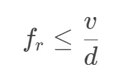
Rule:
: Scan speed, : Spot diameter.
-
-
Scan Speed:
-
Low speed (<500mm/s) ensures pulse overlap (>80%) but increases HAZ.
-
High speed (>1000mm/s) reduces heat input, requiring higher pulse energy.
-
-
Spot Diameter:
-
Small spots (<30μm) enable high precision, needing high-precision galvanometers.
-
3. Auxiliary Parameters
-
Assist Gas:
-
N₂: Inert environment minimizes oxidation and removes debris.
-
Compressed Air: Cost-effective but may introduce contamination.
-
Pressure Optimization: 0.2–0.5MPa; excessive pressure causes turbulent walls.
-
-
Focal Position:
-
Positive Defocus (+50–100μm): Enhances depth control and reduces taper.
-
Negative Defocus: Increases suRFace energy density for thin substrates.
-
III. Quality Evaluation & Feedback Control
-
Hole Diameter Consistency:
-
Tolerance: ±5μm (for 50μm holes), adjusted via real-time CCD monitoring.
-
-
Taper Control:
-
Target taper angle ≤5°, achieved via helical drilling or beam shaping.
-
-
HAZ Suppression:
-
UV lasers with short pulses achieve HAZ <10μm.
-
-
Wall Roughness:
-
Ra ≤2μm, optimized by gas flow and pulse overlap.
-
IV. Typical Parameters (Al₂O₃ Substrate)
| Parameter | UV Laser (355nm) | CO₂ Laser (10.6μm) |
|---|---|---|
| Pulse Energy | 0.05–0.1mJ | 1–5mJ |
| Pulse Width | 10–30ns | 100–200ns |
| Repetition Rate | 30–50kHz | 5–10kHz |
| Scan Speed | 800–1200mm/s | 200–500mm/s |
| Spot Diameter | 20–30μm | 100–150μm |
| Assist Gas | N₂ (0.3MPa) | Compressed Air (0.2MPa) |
| Max Depth | ≤0.5mm | ≤2mm |
V. Failure Modes & Solutions
-
Edge Cracks: Reduce pulse energy, increase repetition rate.
-
Residue: Boost gas pressure or apply clean pulses.
-
Excessive Taper: Adjust defocus or use Top-Hat beam shaping.