 PCB
PCB FPC
FPC Rigid-Flex
 FR-4
FR-4 HDI PCB
 Rogers High-Frequency Board
 PTFE Teflon High-Frequency Board
 Aluminum
 Copper Core
 PCB Assembly
 LED light PCBA
 Memory PCBA
 Power Supply PCBA
 New Energey PCBA
 Communication PCBA
 Industrial Control PCBA
 Medical Equipment PCBA
 Testing Service
 PCBA Testing Service
 Certification Application
 RoHS Certification Application
 REACH Certification Application
 CE Certification Application
 FCC Certification Application
 CQC Certification Application
 UL Certification Application
 Transformers, Inductors
 High Frequency Transformers
 Low Frequency Transformers
 High Power Transformers
 Conversion Transformers
 Sealed Transformers
 Ring Transformers
 Inductors
 Wires,Cables Customized
 Network Cables
 Power Cords
 Antenna Cables
 Coaxial Cables
 Net Position Indicator
 Solar AIS net position indicator
 Capacitors
 Connectors
 Diodes
 Embedded Processors & Controllers
 Digital Signal Processors (DSP/DSC)
 Microcontrollers (MCU/MPU/SOC)
 Programmable Logic Device(CPLD/FPGA)
 Communication Modules/IoT
 Resistors
 Through Hole Resistors
 Resistor Networks, Arrays
 Potentiometers,Variable Resistors
 Aluminum Case,Porcelain Tube Resistance
 Current Sense Resistors,Shunt Resistors
 Switches
 Transistors
 Power Modules
 Isolated Power Modules
 AC-DC Power Modules
 DC-AC Module(Inverter)
 RF and Wireless
What are SMT Moisture - Sensitive Devices (MSD) and How to Control Them?(一)
2025-05-25
1. Introduction to Moisture - Sensitive Devices
Non - hermetic suRFace - mount devices (SMD) are prone to absorb moisture in a humid environment. During the reflow soldering process, the absorbed moisture inside the device vaporizes and expands at high temperatures, which may lead to reliability defects such as delamination or damage to the internal structure of the device. Surface - mount devices with such moisture - absorbing characteristics are defined as moisture - sensitive devices (MSD).
1) The moisture - sensitive characteristics of MSD are determined by the following factors:
- A. Internal structure of the device: Determines the moisture - sensitivity level of the device, including: encapsulation material, thickness, and volume.
- B. External environment of the device: Determines the amount of moisture absorbed inside the device, including: external environment temperature, humidity, and exposure time in a humid environment.
- C. Single - board assembly process: Determines the degree of damage to the moisture inside the device, including: peak reflow soldering temperature, etc.
2) Notes:
- 1.1 Plastic and other non - hermetic packaged SMDs are the key focus of moisture - sensitivity control. Hermetic packaged SMDs such as metal and ceramic are not covered by this specification.
- 1.2 The reflow soldering processes defined in this specification include: infrared/IR, convection, vapor - phase reflow, hot - air rework tools, and immersion wave soldering, etc.
- 1.3 The moisture - sensitive characteristics are clearly defined as the impact of high - temperature soldering on MSD. When the surface temperature of the encapsulation during soldering is <200℃, it is not within the scope of this specification.
- 1.4 J - STD - 033C newly incorporates the J - STD - 075 process soldering sensitivity level (high - temperature resistance and cleaning, etc.). Considering operational feasibility, this specification does not incorporate it.
2. Definition of Moisture - Sensitivity Levels
2.1 MSL Standard Definition
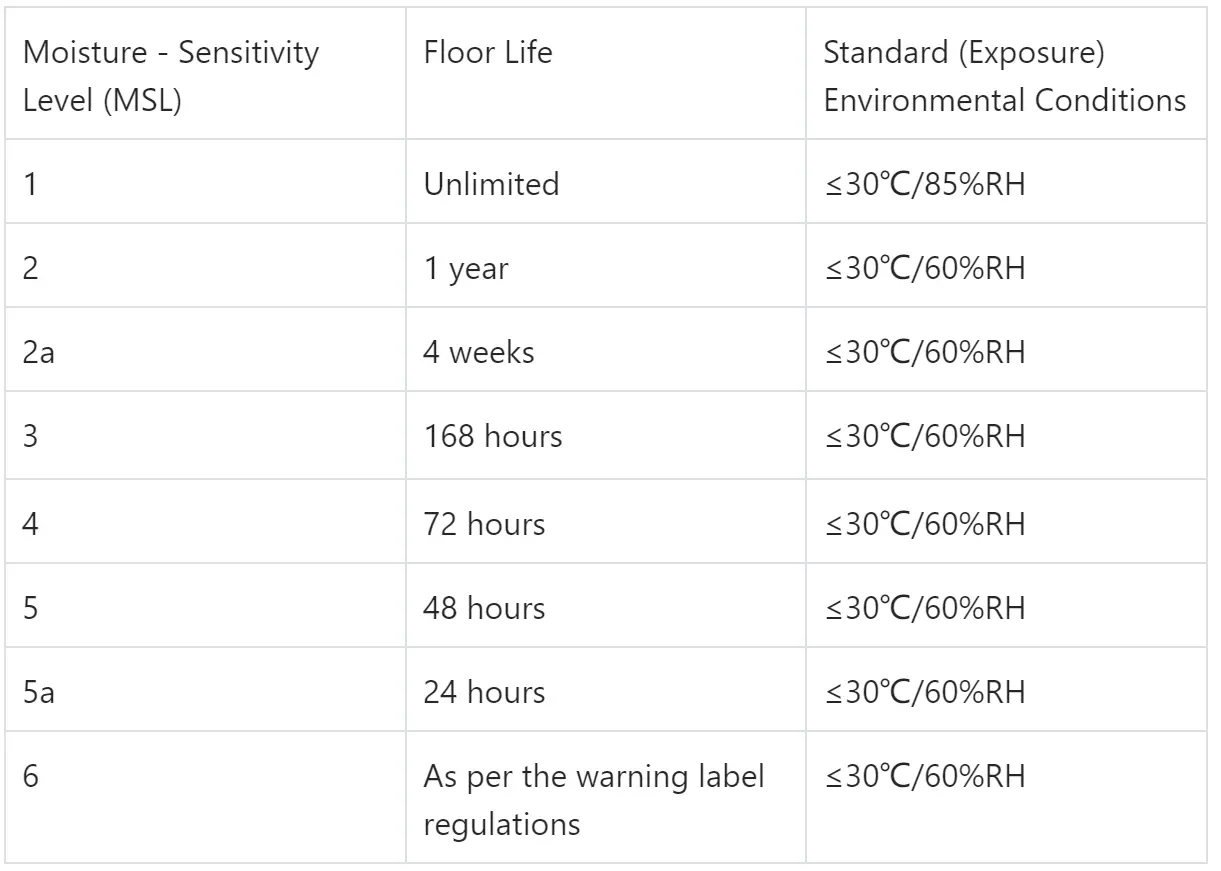
According to the IPC/JEDEC J - STD - 020 standard, the moisture - sensitivity level (MSL) of a device is defined based on its different moisture - absorption capabilities. See Table 1 below for details:
According to the IPC/JEDEC J - STD - 020 standard, the moisture - sensitivity level (MSL) of a device is defined based on its different moisture - absorption capabilities. See Table 1 below for details:
Table 1. MSL Standard Definition
Notes:
- 2.1.1 The company prohibits the selection of MSL = 6 moisture - sensitive devices.
- 2.1.2 The MSL of different manufacturers under the same code may not be consistent. The moisture - sensitivity in PDM follows the device model, not the code. In actual production, the moisture - sensitivity level on the material packaging shall prevail.
2.2 MSL Classification Test Procedure
Before the test is carried out, the MSL must be determined based on the characteristics of the device encapsulation material. Conditions such as the test immersion time and peak reflow soldering temperature are specified according to the determined MSL. If all device samples pass the test, the device meets the requirements of the determined MSL; if device failures are found during the test, the device does not meet the requirements of the determined MSL, and the determined MSL level must be reduced and the test must be repeated. See Figure 1 below for the detailed procedure:
Before the test is carried out, the MSL must be determined based on the characteristics of the device encapsulation material. Conditions such as the test immersion time and peak reflow soldering temperature are specified according to the determined MSL. If all device samples pass the test, the device meets the requirements of the determined MSL; if device failures are found during the test, the device does not meet the requirements of the determined MSL, and the determined MSL level must be reduced and the test must be repeated. See Figure 1 below for the detailed procedure:
After determining the MSL, the following steps are carried out in sequence:
- Initial electrical test
- Initial optical (40X) inspection
- Initial ultrasonic scanning
- Baking (125℃ for 24 hours)
- Moisture soaking
- Reflow soldering
- Final optical (40X) inspection
- Final electrical test
- Final ultrasonic scanning
The above is applicable to the new classification or recertification requirements of the supplier's MSL (also applicable to the company's MSL verification).
1) Requirements for test samples:
- A. 11 pcs/MSL level for new classification, 22 pcs/MSL level for recertification;
- B. Samples must include 2 non - consecutive packaging batches.
2) Criteria for device failure:
- A. External cracks under a 40X optical microscope;
- B. Failure of electrical performance testing;
- C. Internal cracks penetrate the bonding wires, internal and external pad areas; or internal cracks extend from the outer lead finger to the inner lead finger, die, and paddle areas; or internal cracks extend outward beyond 2/3 of the interface length;
- D. Visible defects such as changes in the shape of the encapsulation, swelling, or bulging.
Notes:
- 2.2.1 Term definitions: Cracks occur inside a certain material of the encapsulation; Delamination occurs between the interfaces of different materials of the encapsulation.
- 2.2.2 The delamination of the device before and after the reflow soldering test is not a direct criterion for failure. Refer to the DPA specification of each device (such as IC) for details.
- 2.2.3 After the manufacturer changes the MSL, it must provide re - classification test data and issue a PCN. For inventory materials, it is recommended that the manufacturer directly return them to the warehouse or re - dry and repackage them according to the changed MSL and attach labels.