 PCB
PCB FPC
FPC Rigid-Flex
 FR-4
FR-4 HDI PCB
 Rogers High-Frequency Board
 PTFE Teflon High-Frequency Board
 Aluminum
 Copper Core
 PCB Assembly
 LED light PCBA
 Memory PCBA
 Power Supply PCBA
 New Energey PCBA
 Communication PCBA
 Industrial Control PCBA
 Medical Equipment PCBA
 Testing Service
 PCBA Testing Service
 Certification Application
 RoHS Certification Application
 REACH Certification Application
 CE Certification Application
 FCC Certification Application
 CQC Certification Application
 UL Certification Application
 Transformers, Inductors
 High Frequency Transformers
 Low Frequency Transformers
 High Power Transformers
 Conversion Transformers
 Sealed Transformers
 Ring Transformers
 Inductors
 Wires,Cables Customized
 Network Cables
 Power Cords
 Antenna Cables
 Coaxial Cables
 Net Position Indicator
 Solar AIS net position indicator
 Capacitors
 Connectors
 Diodes
 Embedded Processors & Controllers
 Digital Signal Processors (DSP/DSC)
 Microcontrollers (MCU/MPU/SOC)
 Programmable Logic Device(CPLD/FPGA)
 Communication Modules/IoT
 Resistors
 Through Hole Resistors
 Resistor Networks, Arrays
 Potentiometers,Variable Resistors
 Aluminum Case,Porcelain Tube Resistance
 Current Sense Resistors,Shunt Resistors
 Switches
 Transistors
 Power Modules
 Isolated Power Modules
 AC-DC Power Modules
 DC-AC Module(Inverter)
 RF and Wireless
Part VI: Wave Soldering - Formation and Application of Wave Dynamics Theory
Part VI: Wave Soldering - Formation and ApplICation of Wave Dynamics Theory
XII. Design of Solder Wave Shape and Its Impact on Wave Soldering Effect
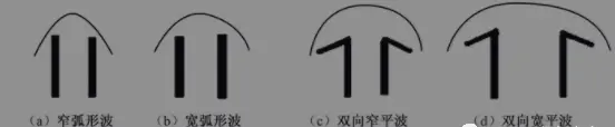
The greatest contribution of solder wave dynamics lies in providing theoretical guidance and a basis for designing the shape of solder waves. The nozzle contour controls the shape of the solder wave, thereby controlling the dynamics of the solder wave. Currently, various shapes of solder waves are popular in wave soldering systems worldwide (as shown in the diagram below), and each design claims to have optimal solder wave dynamics characteristics. Here, we select a few of the most representative waveforms and initially analyze their characteristics from the perspective of solder wave dynamics.
Narrow Arc Wave: As shown in (a) below, this was a commonly used solder waveform in the early stages of wave soldering process development. The nozzle structure that forms this wave is relatively simple. Due to the narrow wave peak and insufficient heat supply, production efficiency is low, and pulling and bridging are prone to occur during soldering. A typical application case of this waveform is the world's first industrial wave soldering machine developed by Fry's Metal in the UK. Its main operating parameters are: maximum wave height of 12.7mm, maximum nozzle outlet height above the liquid suRFace of 19.1mm, depth of the PCB substrate pressed into the wave peak of 0.8mm, and maximum PCB substrate conveyor speed during soldering of 120cm/min. Clearly, its production efficiency is very low. The only way to improve the thermal characteristics of the solder wave and increase production efficiency is to increase the wave width, leading to the emergence of the wide arc wave.
Wide Arc Wave: As shown in (b) below. To increase the wave width for the arc wave nozzle structure, it can only be achieved by increasing the pump's thrust. Excessively high rotational speed or excessive driving torque of the pump's drive system not only easily leads to increased wear on rotating parts and complicates the structure but also exacerbates the transition of solder fluid to turbulence, worsening wave stability and accelerating solder oxidation, which is undesirable.
Bidirectional Flat Wave: To increase the wave width without increasing the rotational speed and torque of the wave drive system, nozzle structures as shown in (c) and (d) below were designed. The bidirectional wide flat wave overcomes the shortcomings of the arc wave. This waveform has a distinct region at the top where the velocity is zero, which is very beneficial for eliminating pulling and bridging. Moreover, through the action of the expansion plate, the wave width can be made very wide, reaching 80mm on some models, significantly improving production efficiency. Therefore, the bidirectional wide flat wave is still widely used in many current models.
Asymmetric Bidirectional Wide Flat Wave: The symmetric bidirectional wide flat wave shown in (c) and (d) above has symmetric bidirectional flow division with equal flow velocities. When the PCB enters the wave peak, due to the flow resistance of the substrate, the surface flow velocity in the direction opposite to the PCB conveyor slows down, the boundary layer thickens, the zero-velocity zone narrows and becomes blurred, and the PCB exit point from the wave peak is difficult to control. Macroscopically, this results in a weak scrubbing effect on the PCB, which is unfavorable for eliminating pulling and bridging. To enhance its reverse scrubbing effect and further suppress pulling and bridging, the waveform needs to be designed as an asymmetric bidirectional wide flat wave, as shown in Figures 2.14 (g), (h), and (i) below. This increases the flow rate and velocity of the fluid in the direction opposite to the PCB, not only significantly enhancing the scrubbing effect on the PCB but also facilitating accurate adjustment of the position of the zero-velocity zone to coincide with the PCB exit point, thereby ensuring the optimal conditions required during the soldering process. The most representative waveforms are:
(1) Z-shaped Wave: The Z-shaped wave is an improved design by the US company Hollis to reduce defects such as solder bridging and pulling (Hollis patent). The specific method involves increasing the width of the wave surface, using an inclined conveyor belt, and adopting oil-mixed solder waves. However, due to issues such as odor emission and smoke exhaust from the oil, later improvements were made towards a dry Z-shaped wave (without oil), as shown in (i) below.
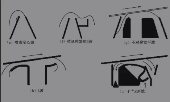
(2) λ-shaped Wave: The standard λ-shaped wave, shown in the diagram below, is a patented technology of US company Electrovert. It is effective in reducing pulling and bridging and does not require oil blending. This waveform is designed using the interrelationship between thermodynamics and fluid mechanics. As seen in the diagram below, the PCB begins to come into contact with the wave peak under force at a high-speed point, so the scrubbing effect of the solder is also optimal. By placing a baffle in front of the nozzle to control the shape of the wave peak, the velocity characteristics of the wave peak are also controlled, forming a large area with a relative velocity of zero in front of the nozzle. Therefore, when using a conveyor with a wide adjustable range of inclination angles, it is more convenient to control the detachment of the PCB at the point on the wave peak where the relative velocity is zero. The post-heat effect produced by the molten liquid solder immediately behind it allows the surface tension of the solder at the detachment point to maintain a minimum level for sufficient time, which helps reduce solder pulling at the solder joints. It is claimed that with this nozzle, even when the conveyor speed exceeds 6m/min, successful wave soldering without pulling can be achieved, with a maximum wave height of up to 12.7mm.
Part V: Wave Soldering - Formation and Application of Wave Dynamics Theory
Part IV: The formation and application of wave soldering wave dynamics theory
Part III:Wave Soldering - Formation and Application of Wave Dynamics Theory