 PCB
PCB FPC
FPC Rigid-Flex
 FR-4
FR-4 HDI PCB
 Rogers High-Frequency Board
 PTFE Teflon High-Frequency Board
 Aluminum
 Copper Core
 PCB Assembly
 LED light PCBA
 Memory PCBA
 Power Supply PCBA
 New Energey PCBA
 Communication PCBA
 Industrial Control PCBA
 Medical Equipment PCBA
 Testing Service
 PCBA Testing Service
 Certification Application
 RoHS Certification Application
 REACH Certification Application
 CE Certification Application
 FCC Certification Application
 CQC Certification Application
 UL Certification Application
 Transformers, Inductors
 High Frequency Transformers
 Low Frequency Transformers
 High Power Transformers
 Conversion Transformers
 Sealed Transformers
 Ring Transformers
 Inductors
 Wires,Cables Customized
 Network Cables
 Power Cords
 Antenna Cables
 Coaxial Cables
 Net Position Indicator
 Solar AIS net position indicator
 Capacitors
 Connectors
 Diodes
 Embedded Processors & Controllers
 Digital Signal Processors (DSP/DSC)
 Microcontrollers (MCU/MPU/SOC)
 Programmable Logic Device(CPLD/FPGA)
 Communication Modules/IoT
 Resistors
 Through Hole Resistors
 Resistor Networks, Arrays
 Potentiometers,Variable Resistors
 Aluminum Case,Porcelain Tube Resistance
 Current Sense Resistors,Shunt Resistors
 Switches
 Transistors
 Power Modules
 Isolated Power Modules
 AC-DC Power Modules
 DC-AC Module(Inverter)
 RF and Wireless
Part IV: The formation and application of wave soldering wave dynamics theory
Part IV: The formation and applICation of wave soldering wave dynamics theory
Section 7: The Physical Nature of the Role of Protective Oil in Wave Soldering
Injecting oil into the solder wave has a significant impact on the mechanical state of the exit point. Usually, the protective oil is injected into the pump impeller and enters the solder wave crest, such as the early Z-shaped solder wave crest system of Hollis Company in the United States, or the 6TF series hollow wave jet system produced by KIRSTN Company in Switzerland, which sprays oil onto the solder wave crest suRFace. The entire wave crest is covered with oil layers, and the real purpose of mixing the molten solder with the protective oil is to reduce the surface tension of the molten solder at the PCB exit from the wave crest, minimizing the thin layer of solder at the peeling site to eliminate solder joint tipping and bridging. When the welding spot leaves the peak, it is coated with a layer of oil, which prevents oxidation and makes the welding spot particularly bright, facilitating the inspection of defects such as microcracks in the welding spot. Due to the trend of reducing the tipping of solder joints, the speed of the transmission device can be accelerated, thereby improving production efficiency. Reducing surface tension can increase the ability of liquid solder to wet PCB copper pads, so it can also appropriately reduce the temperature of the solder wave by about 10°C without affecting the soldering effect.
The oil injection process has been eliminated in new equipment in recent years for the following reasons:
● When using protective oil for wave soldering, the oil will be wrapped in the solder joints, affecting the mechanical and electrical properties of the solder joints and potentially leading to the formation of corrosive acidic residues;
● It will make the PCB components to be welded dirty and with oily coating, which is difficult to clean;
● When using protective oil for wave soldering, it must be cleaned after soldering, which is not conducive to environmental protection.
Section 8: Sufficient and necessary conditions for obtaining a solder joint without a pointed tip
The following analysis aims to obtain the sufficient and necessary conditions for obtaining a solder joint without a pointed tip, based on the velocity distribution of the droplets at the PCB's peak of detachment, as shown in the figure below.
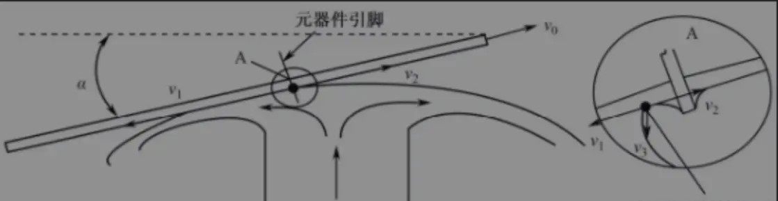
The peeling condition of PCB pads and wave soldering.
Let the PCB pinching speed be v0, the stripping flow rate of the solder on the surface of the wave peak at point A in the direction opposite to the PCB be v1, and the drooping speed of the solder on the solder joint due to gravity and other factors be vg. Analyze based on the flow state and force conditions of the droplet at point A.
The sufficient and necessary conditions for obtaining a solder joint without a pointed tip are as follows.
① Sufficient condition: vg=0, where vg is the drooping speed of the solder droplet, which is affected by the angle α of the PCB's exit from the solder wave crest, the PCB's pinching speed v0, the solder flow rate v1 in the direction opposite to the PCB, the surface tension of the solder, and the wetting force of the component pins.
② Necessary conditions: v1>v, 0v1>0, v0 - PCB exit speed, i.e. pinch speed; v1 - The flow speed of the solder in the direction opposite to the PCB movement, which is affected by factors such as the temperature of the solder, the surface state of the PCB, the state of the component leads, and the performance of the flux. Using a tilted pinch-off method in conjunction with a wide wave crest allows the PCB to exit from or near the wave crest at a relative speed of zero, which gives the solder surface tension sufficient time to fully drag the excess solder back to the wave crest.
Part III:Wave Soldering - Formation and Application of Wave Dynamics Theory