 PCB
PCB FPC
FPC Rigid-Flex
 FR-4
FR-4 HDI PCB
 Rogers High-Frequency Board
 PTFE Teflon High-Frequency Board
 Aluminum
 Copper Core
 PCB Assembly
 LED light PCBA
 Memory PCBA
 Power Supply PCBA
 New Energey PCBA
 Communication PCBA
 Industrial Control PCBA
 Medical Equipment PCBA
 Testing Service
 PCBA Testing Service
 Certification Application
 RoHS Certification Application
 REACH Certification Application
 CE Certification Application
 FCC Certification Application
 CQC Certification Application
 UL Certification Application
 Transformers, Inductors
 High Frequency Transformers
 Low Frequency Transformers
 High Power Transformers
 Conversion Transformers
 Sealed Transformers
 Ring Transformers
 Inductors
 Wires,Cables Customized
 Network Cables
 Power Cords
 Antenna Cables
 Coaxial Cables
 Net Position Indicator
 Solar AIS net position indicator
 Capacitors
 Connectors
 Diodes
 Embedded Processors & Controllers
 Digital Signal Processors (DSP/DSC)
 Microcontrollers (MCU/MPU/SOC)
 Programmable Logic Device(CPLD/FPGA)
 Communication Modules/IoT
 Resistors
 Through Hole Resistors
 Resistor Networks, Arrays
 Potentiometers,Variable Resistors
 Aluminum Case,Porcelain Tube Resistance
 Current Sense Resistors,Shunt Resistors
 Switches
 Transistors
 Power Modules
 Isolated Power Modules
 AC-DC Power Modules
 DC-AC Module(Inverter)
 RF and Wireless
SMT BGA Solder Joint Quality Inspection Technology (Part 1)
2025-04-25
BGA in the development of assembly processes or as an audit mechanism during production, and the inspection techniques used at different stages. The following table provides some recommendations on the applICability of inspection methods.
| Method | Process Development | In - line Production | Failure Analysis | Process Audit | NPI or Small - batch Production |
|---|---|---|---|---|---|
| Optical Inspection | Excellent | Good | Excellent | Good | Good |
| Manual X - ray | Excellent | Good | Excellent | Good | Excellent |
| Automatic Transmission X - ray | Excellent | Excellent | Good | Good | Good |
| Automatic Cross - sectional X - ray | Excellent | Excellent | Excellent | Good | Good |
| Scanning Acoustic Microscope | Excellent | Fair | Good | Good | Fair |
| Gap Height Measurement | Fair | Fair | Good | Good | Fair |
| Automatic Optical Inspection | Solder Paste Volume | Component Identification, Solder Paste Volume | Not Applicable | Component Identification, Solder Paste Volume | Component Identification, Solder Paste Volume |
| Destructive Analysis | Good | Poor | Excellent | Fair | Fair |
I. X - ray
X - ray inspection is typically used when solder joints are highly obscured and out of sight, and when a large number of solder joints are untestable. Examples of untestable solder joints are redundant connections and back - to - back BGAs, where the vias in the BGA fan - out are difficult to access and there is not enough space to set additional test points. The X - ray method can serve as a supplement to the selected testing process and provide rapid feedback to the production line. Depending on the capabilities of the X - ray system used, X - rays can detect soldering - related defects such as bridging, open solder joints, insufficient solder, and excessive solder. Other defects such as missing solder balls, misalignment, and the popcorn effect in the package can also be identified. In addition to defect detection, X - rays can also provide trend analysis of solder volume and solder joint shape. X - ray is the only non - destructive method for detecting voids in BGA solder joints.
Figure 1 below shows the principle of an X - ray device using X - rays above the sample under test; in some devices, the X - ray tube is below the sample or at an angle to the sample. The general features given in this figure are applicable to most X - ray systems. X - ray inspection has become a recognized tool for evaluating and analyzing solder joints and for monitoring the reflow soldering process. X - ray inspection technology can be most effectively applied by understanding the principles of X - ray image acquisition.
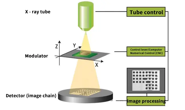
Figure 1: Principle of X - ray Device
X - rays are effective in confirming the integrity of BGA solder bonds and in monitoring the reflow soldering process. The following knowledge can be used to most effectively apply X - ray inspection technology:
X - rays are effective in confirming the integrity of BGA solder bonds and in monitoring the reflow soldering process. The following knowledge can be used to most effectively apply X - ray inspection technology:
- Principles of X - ray image acquisition
- X - ray image analysis (based on the reflow soldering process)
When using X - rays, it is necessary to pay attention to over - exposure of vulnerable materials or components. Figure 2 below shows the X - ray image characteristics of voids in the BGA connection inteRFace or missing solder balls.
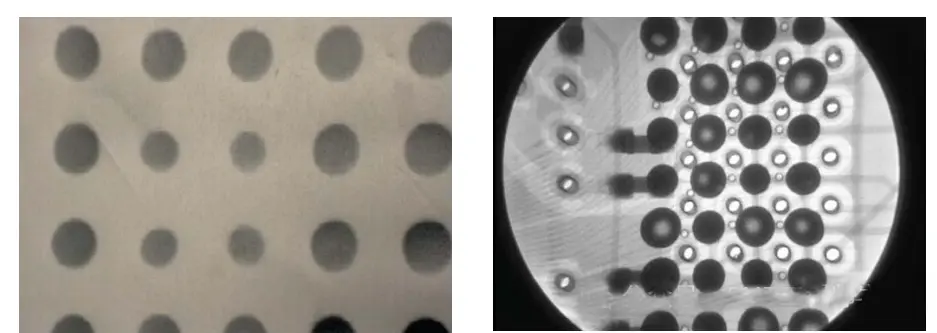
Figure 2: X - ray Image Characteristics of Voids in BGA Connection Interface or Missing Solder Balls