 PCB
PCB FPC
FPC Rigid-Flex
 FR-4
FR-4 HDI PCB
 Rogers High-Frequency Board
 PTFE Teflon High-Frequency Board
 Aluminum
 Copper Core
 PCB Assembly
 LED light PCBA
 Memory PCBA
 Power Supply PCBA
 New Energey PCBA
 Communication PCBA
 Industrial Control PCBA
 Medical Equipment PCBA
 Testing Service
 PCBA Testing Service
 Certification Application
 RoHS Certification Application
 REACH Certification Application
 CE Certification Application
 FCC Certification Application
 CQC Certification Application
 UL Certification Application
 Transformers, Inductors
 High Frequency Transformers
 Low Frequency Transformers
 High Power Transformers
 Conversion Transformers
 Sealed Transformers
 Ring Transformers
 Inductors
 Wires,Cables Customized
 Network Cables
 Power Cords
 Antenna Cables
 Coaxial Cables
 Net Position Indicator
 Solar AIS net position indicator
 Capacitors
 Connectors
 Diodes
 Embedded Processors & Controllers
 Digital Signal Processors (DSP/DSC)
 Microcontrollers (MCU/MPU/SOC)
 Programmable Logic Device(CPLD/FPGA)
 Communication Modules/IoT
 Resistors
 Through Hole Resistors
 Resistor Networks, Arrays
 Potentiometers,Variable Resistors
 Aluminum Case,Porcelain Tube Resistance
 Current Sense Resistors,Shunt Resistors
 Switches
 Transistors
 Power Modules
 Isolated Power Modules
 AC-DC Power Modules
 DC-AC Module(Inverter)
 RF and Wireless
Controlling Etching Speed and Conveyor Speed Matching to Avoid Circuit Offset in Roll-to-Roll Flexible PCB Etching
2025-10-26
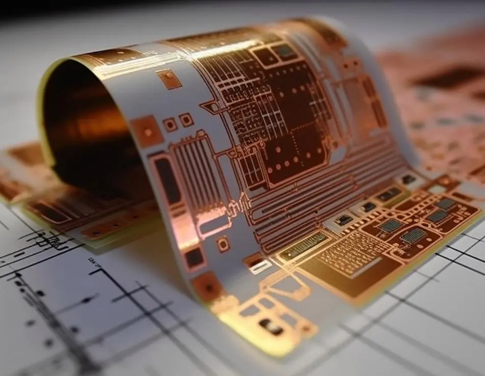
Roll-to-roll (R2R) processing is a high-throughput manufacturing method for flexible PCBs (FPCs), ideal for mass-producing lightweight, bendable electronics such as wearable sensors, flexible displays, and automotive flex circuits. Unlike batch processing of rigid PCBs, R2R FPC etching involves continuously feeding a flexible substrate roll (typically polyimide, PI, or polyester) through an etching system to pattern copper layers into circuits.
A critical defect in R2R etching is circuit offset—a misalignment between the etched copper pattern and the FPC’s design coordinates. Offset manifests as:
- Lateral shift: Circuits deviate horizontally from the substrate’s centerline.
- Longitudinal distortion: Circuit features stretch or compress along the direction of the substrate’s movement.
- Pattern skewing: Circuit shapes (e.g., traces, pads) become tilted relative to the substrate’s edges.
Circuit offset occurs when etching speed (the rate at which the etchant removes copper, μm/min) and conveyor speed (the rate at which the substrate moves through the etcher, m/min) are mismatched. Even a 5% mismatch can cause 0.1mm offset for fine-pitch circuits (0.2mm line width/spacing), rendering FPCs unusable for high-density applications. Thus, precise control of this speed relationship is essential to maintain etching yield (>95%) and circuit accuracy.
2. Core Mechanisms of Circuit Offset from Speed Mismatch
To address offset, it is first necessary to understand how speed mismatch drives misalignment:
2.1 Etching Speed: Copper Removal Kinetics
Etching speed depends on the etchant’s concentration, temperature, and spray pressure. For the alkaline cupric chloride etchants commonly used in R2R FPC processing:
- Higher etchant concentration (Cu²⁺ > 120g/L) or temperature (45–50℃) increases etching speed (20–30μm/min).
- Lower concentration (Cu²⁺ < 80g/L) or temperature (30–35℃) decreases etching speed (5–15μm/min).
If etching speed is too fast relative to conveyor speed, the etchant over-removes copper from circuit edges, causing undercut—a form of offset where trace widths narrow beyond design tolerances.
2.2 Conveyor Speed: Substrate Movement Stability
Conveyor speed determines how long the substrate is exposed to the etchant (dwell time). For an etcher with a 1m-long etching chamber:
- Dwell time = Chamber length / Conveyor speed (e.g., 1m / 5m/min = 12 seconds).
If conveyor speed is inconsistent (fluctuations >±2%), dwell time varies across the substrate. This leads to non-uniform etching: some areas are over-etched (offset due to undercut), while others are under-etched (residual copper causing short circuits).
2.3 Speed Mismatch Dynamics
The ideal relationship is:

For a 18μm-thick copper layer and 12-second dwell time, the required etching speed is 90μm/min (18μm / 0.2min). A mismatch here causes two types of offset:
- Over-etching (etching speed > required): Trace edges are eroded, width decreases by 5–10μm (offset relative to design).
- Under-etching (etching speed < required): Residual copper remains between traces, creating "bridges" (offset due to incorrect pattern definition).
3. Speed Matching Control Strategies for R2R Etching
Achieving stable speed matching requires integrating real-time monitoring, process parameter calibration, and mechanical stabilization of the R2R system:
3.1 Pre-Processing: Baseline Speed Calibration
Before starting production, establish a calibrated speed relationship based on FPC specifications:
- Step 1: Define target dwell time: Calculate based on copper thickness and etchant capabilities. For 12μm copper and 60μm/min etching speed, dwell time = 12μm / 60μm/min = 0.2min (12 seconds).
- Step 2: Set conveyor speed: For a 0.8m etching chamber, conveyor speed = 0.8m / 0.2min = 4m/min.
- Step 3: Validate with test strips: Etch FPC test strips with known copper thickness. Measure trace width using a laser profilometer—width deviation should be ≤±3μm (acceptable for 0.2mm traces).
3.2 Real-Time Etching Speed Monitoring
Use in-line sensors to adjust etching speed dynamically and maintain matching with conveyor speed:
- Copper concentration sensors: Install inline UV-Vis spectrometers to monitor Cu²⁺ concentration (range: 80–150g/L). If concentration drops by >10g/L (slowing etching speed), automatically add fresh etchant to restore concentration and etching speed.
- Etch rate monitors: Place a rotating copper coupon (same thickness as FPC) in the etchant bath. Measure coupon weight loss per minute to calculate real-time etching speed. If speed deviates by >5% from target, adjust etchant temperature (±1℃) to correct.
- Thermal controllers: Maintain etchant temperature within ±0.5℃ (e.g., 45±0.5℃) using PID (proportional-integral-derivative) controllers. Temperature fluctuations of ±1℃ change etching speed by ~8%, so tight control is critical.
3.3 Conveyor Speed Stability and Synchronization
Conveyor speed fluctuations are a major source of offset—stabilize movement with these measures:
- Servo motor drives: Replace AC motors with servo motors (position accuracy ±0.1mm/m) to maintain conveyor speed within ±1% of setpoint. Servo systems use encoder feedback to correct speed deviations in real time.
- Tension control: Install dancer rollers and load cells to maintain constant substrate tension (5–10N for PI substrates). Tension fluctuations (>±2N) cause substrate stretching/compression, leading to longitudinal offset. The dancer system adjusts conveyor speed slightly (±0.2m/min) to keep tension stable.
- Chamber length optimization: For high-speed R2R lines (>6m/min), use longer etching chambers (1.5–2m) to increase dwell time. This reduces the required etching speed (e.g., 18μm copper / 0.3min dwell time = 60μm/min vs. 90μm/min for 0.2min), making speed matching easier.
4. Advanced Control for Fine-Pitch FPCs (Line Width < 0.1mm)
Fine-pitch FPCs (e.g., flex circuits for foldable phones) require stricter speed matching (±2% tolerance) to avoid offset. Implement these advanced techniques:
4.1 Machine Vision-Based Pattern Alignment
Install high-resolution cameras (5μm/pixel) before and after the etching chamber:
- Pre-etch inspection: Capture images of the photoresist pattern and compare to the design to detect pre-existing substrate misalignment. Adjust conveyor speed by ±0.1m/min to compensate.
- Post-etch inspection: Measure etched circuit positions using image analysis software. If offset exceeds ±2μm, send feedback to the etchant temperature controller to adjust etching speed.
4.2 Dual-Zone Etching Chambers
Divide the etching chamber into two zones with independent etchant spray systems:
- Zone 1 (Pre-etch): Low etching speed (30–40μm/min) to define circuit edges.
- Zone 2 (Main etch): Target etching speed (calculated per dwell time) to remove bulk copper.
This reduces edge erosion (undercut) by 40–50% compared to single-zone etching, even with minor speed mismatches.
4.3 Etchant Recirculation and Filtration
Use a closed-loop etchant recirculation system with 5μm Filters:
- Recirculate etchant at 10–15L/min to ensure uniform concentration and temperature across the chamber. Dead zones (low flow areas) cause local speed variations and offset.
- Filter out copper sludge (byproduct of etching) to prevent nozzle clogging. Clogged nozzles reduce spray pressure, lowering etching speed in localized areas and causing pattern distortion.
5. Validation and Quality Assurance
To confirm speed matching is effective and offset is minimized, implement these tests:
5.1 Circuit Offset Measurement
- Use a coordinate measuring machine (CMM) with a vision probe to measure the X-Y coordinates of 20–30 circuit features (e.g., pad centers, trace endpoints) across the FPC roll.
- Calculate offset as the maximum deviation from design coordinates. Acceptable offset: ≤±5μm for fine-pitch FPCs (<0.1mm line width), ≤±10μm for standard FPCs.
5.2 Etching Uniformity Test
- Cut 10 samples from different positions of the etched roll (start, middle, end). Measure copper thickness at 5 points per sample using an X-ray fluorescence (XRF) analyzer.
- Thickness variation should be ≤±1μm, indicating uniform etching (no speed mismatch-induced over/under-etching).
5.3 Mechanical Flex Testing
- Subject etched FPCs to 10,000 bend cycles (±90°) to ensure offset does not cause mechanical failure. Offset-induced narrow traces (<0.09mm for 0.1mm design) will crack after <5,000 cycles.
6. Conclusion
Controlling etching speed and conveyor speed matching in R2R flexible PCB etching is a dynamic process that requires precise calibration, real-time monitoring, and mechanical stabilization. The key steps are:
- Calculate target etching speed and conveyor speed based on copper thickness and dwell time.
- Use in-line sensors (concentration, temperature, etch rate) to adjust etching speed dynamically.
- Stabilize conveyor speed with servo motors, tension control, and optimized chamber design.
For fine-pitch FPCs, advanced techniques like machine vision alignment and dual-zone etching further reduce offset to ≤±5μm. Validation via CMM measurement and flex testing ensures the final product meets circuit accuracy and reliability requirements.
As R2R FPCs trend toward thinner copper (6–12μm) and finer pitches (<0.05mm), future innovations—such as AI-driven predictive control (using machine learning to anticipate speed deviations) and plasma-assisted etching (for ultra-uniform speed)—will push speed matching precision to ±1%, enabling even more advanced flexible electronics. For manufacturers, mastering speed matching is not just a quality requirement—it is the cornerstone of high-yield, cost-effective R2R FPC production.