PCB
PCB FPC
FPC Rigid-Flex
 FR-4
FR-4 HDI PCB
 Rogers High-Frequency Board
 PTFE Teflon High-Frequency Board
 Aluminum
 Copper Core
 PCB Assembly
 LED light PCBA
 Memory PCBA
 Power Supply PCBA
 New Energey PCBA
 Communication PCBA
 Industrial Control PCBA
 Medical Equipment PCBA
 Testing Service
 PCBA Testing Service
 Certification Application
 RoHS Certification Application
 REACH Certification Application
 CE Certification Application
 FCC Certification Application
 CQC Certification Application
 UL Certification Application
 Transformers, Inductors
 High Frequency Transformers
 Low Frequency Transformers
 High Power Transformers
 Conversion Transformers
 Sealed Transformers
 Ring Transformers
 Inductors
 Wires,Cables Customized
 Network Cables
 Power Cords
 Antenna Cables
 Coaxial Cables
 Net Position Indicator
 Solar AIS net position indicator
 Capacitors
 Connectors
 Diodes
 Embedded Processors & Controllers
 Digital Signal Processors (DSP/DSC)
 Microcontrollers (MCU/MPU/SOC)
 Programmable Logic Device(CPLD/FPGA)
 Communication Modules/IoT
 Resistors
 Through Hole Resistors
 Resistor Networks, Arrays
 Potentiometers,Variable Resistors
 Aluminum Case,Porcelain Tube Resistance
 Current Sense Resistors,Shunt Resistors
 Switches
 Transistors
 Power Modules
 Isolated Power Modules
 AC-DC Power Modules
 DC-AC Module(Inverter)
 RF and Wireless
Preventing Thermal Damage to Adjacent Components During Rework of Ultra-Fine Pitch (<0.2mm) Devices
1. Core Thermal Management Strategies
-
Localized Temperature Control:
-
MICro nozzles (ID≤0.5mm) or pulsed laser heating (spot accuracy ±0.05mm)
-
Heat Affected Zone (HAZ) confined within 0.15mm of target component
-
-
Temperature Gradient Design:
-
Target component ramp rate: 3~5°C/s, adjacent component ΔT≤60°C (verified)
-
2. Physical Isolation Techniques
| Protection Method | Implementation | Effectiveness |
|---|---|---|
| Heat Shields | Custom Kovar alloy cover (0.1mm thick) | Reduce adjacent ΔT 40~50°C |
| Phase-Change Material | Bismuth-based alloy coating (mp 138°C) | Absorb >80J/g peak heat |
| Thermal Barriers | High-λ silicone (5 W/mK) injection | Thermal resistance 3~5× |
3. Process Parameter Optimization
-
Equipment Setup:
-
Bottom preheater: 150°C (prevent PCB warpage)
-
Top heater: 280°C±5°C (duration≤15s)
-
-
Gas Control:
-
Nitrogen environment (O₂<100ppm), flow 0.5~1 L/min
-
Vacuum nozzle synchronization (-5kPa) to prevent splashing
-
4. Real-Time Monitoring
| Parameter | Instrument | Specification |
|---|---|---|
| Target Temp | SWIR thermal imager (3μm) | ±2°C @ 0.1mm resolution |
| Adjacent Temp | Micro-thermocouple (Φ0.05mm) | 0.1s response time |
| Solder State | High-speed camera (1000fps) | 5μm/pixel resolution |
5. Failure Prevention
-
Thermal-Sensitive Component Protection:
-
Attach copper heatsinks (0.2mm thick, ≥1.5× component area) to nearby MLCCs
-
Cover crystals with silica aerogel (λ=0.02 W/mK)
-
-
Solder Selection:
-
Use low-melting SAC305 (217°C) or indium alloys (118°C)
-
Avoid bismuth-containing pastes (embrittlement risk)
-
6. Post-Rework Validation
| Test | Criterion | Method |
|---|---|---|
| Electrical Function | Parameter drift ≤±5% | IV curve test |
| Microstructure | No grain growth/IMC thickening | SEM/EDX analysis |
| Mechanical Strength | Shear force ≥85% of original | JESD22-B117 test |
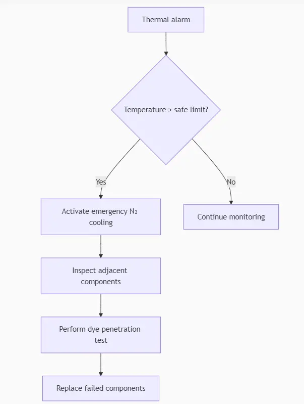
7. Emergency Protocol