 PCB
PCB FPC
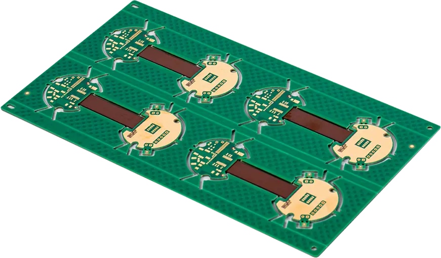
FPC Rigid-Flex
 FR-4
FR-4 HDI PCB
 Rogers High-Frequency Board
 PTFE Teflon High-Frequency Board
 Aluminum
 Copper Core
 PCB Assembly
 LED light PCBA
 Memory PCBA
 Power Supply PCBA
 New Energey PCBA
 Communication PCBA
 Industrial Control PCBA
 Medical Equipment PCBA
 Testing Service
 PCBA Testing Service
 Certification Application
 RoHS Certification Application
 REACH Certification Application
 CE Certification Application
 FCC Certification Application
 CQC Certification Application
 UL Certification Application
 Transformers, Inductors
 High Frequency Transformers
 Low Frequency Transformers
 High Power Transformers
 Conversion Transformers
 Sealed Transformers
 Ring Transformers
 Inductors
 Wires,Cables Customized
 Network Cables
 Power Cords
 Antenna Cables
 Coaxial Cables
 Net Position Indicator
 Solar AIS net position indicator
 Capacitors
 Connectors
 Diodes
 Embedded Processors & Controllers
 Digital Signal Processors (DSP/DSC)
 Microcontrollers (MCU/MPU/SOC)
 Programmable Logic Device(CPLD/FPGA)
 Communication Modules/IoT
 Resistors
 Through Hole Resistors
 Resistor Networks, Arrays
 Potentiometers,Variable Resistors
 Aluminum Case,Porcelain Tube Resistance
 Current Sense Resistors,Shunt Resistors
 Switches
 Transistors
 Power Modules
 Isolated Power Modules
 AC-DC Power Modules
 DC-AC Module(Inverter)
 RF and Wireless
Pressure Difference Control and Deformation Prevention in Rigid-Flex PCB Lamination
I. Core Challenge in Rigid-Flex PCB Lamination: Pressure Adaptation Between Flexible and Rigid Areas
Rigid-Flex Pcbs are formed by laminating rigid substrates (e.g., FR-4) and flexible substrates (e.g., PI) with prepreg. The core challenge lies in their differing physical properties: rigid substrates (elastic modulus ~15-20 GPa) exhibit high compressive strength and minimal deformation, while flexible substrates (elastic modulus ~2-4 GPa) are soft and prone to compression-induced deformation. If uniform pressure is applied during lamination, the rigid area remains stable, but the flexible area may suffer from wrinkles, stretching, or abnormal resin flow from the prepreg. Severe cases can lead to circuit fractures during subsequent bending (increasing failure probability by over 30%).
Thus, precise control of the pressure difference between flexible and rigid areas is essential to balance stress distribution: sufficient pressure must ensure proper resin flow and interlayer adhesion in the rigid area, while excessive pressure on the flexible area must be avoided to prevent deformation. This is a critical quality control point in rigid-flex PCB lamination.
II. Recommended Pressure Difference Range
Based on substrate properties (flexible substrate thickness: 0.05-0.2 mm, rigid substrate thickness: 0.4-1.6 mm), prepreg type (low-resin-flow type, 20%-30% flow), and industry data, the pressure difference between flexible and rigid areas should be controlled within 0.2-0.5 kg/cm², with adjustments based on structural design:
-
Baseline Standard: 0.2-0.5 kg/cm² Pressure Difference
-
Lower Limit (0.2 kg/cm²): If the pressure difference is <0.2 kg/cm², insufficient pressure on the rigid area (e.g., 3.0 kg/cm² rigid vs. 2.9 kg/cm² flexible) may cause inadequate resin flow, reducing interlayer adhesion (<1.2 kN/m) and risking delamination. Board thickness uniformity in the rigid area may deviate by >±0.03 mm, affecting drilling and component mounting accuracy.
-
Upper Limit (0.5 kg/cm²): If the pressure difference is >0.5 kg/cm², overly low pressure on the flexible area (e.g., 3.5 kg/cm² rigid vs. <3.0 kg/cm² flexible) can lead to poor adhesion, causing bubbles (bubble rate >0.5%). Excessive pressure difference may also trigger "pressure migration," where rigid-area pressure spreads to the flexible area, resulting in uneven local pressure and wavy deformation (>0.1 mm/m).
-
-
Adjustments for Different Flexible Area Structures
Flexible Area Structure Pressure Difference (kg/cm²) Rationale No reinforcement, thin substrate (0.05-0.1 mm) 0.2-0.3 Thin substrates have low compressive resistance; smaller pressure difference prevents stretching. Local reinforcement (e.g., steel stiffener) 0.3-0.4 Stiffeners enhance local rigidity, allowing a moderate pressure difference for better bonding. High-density circuits (line width/spacing ≤0.1 mm) 0.4-0.5 Higher pressure difference ensures prepreg fills gaps, avoiding interlayer voids.
III. Implementation Methods: Equipment, Process, and Tooling
To maintain a stable 0.2-0.5 kg/cm² pressure difference, integrate equipment upgrades, process optimization, and tooling support:
-
Equipment Upgrades: Zoned Pressure Systems
-
Use laminators with "flexible pressure Modules" (e.g., airbag laminators) instead of traditional plate laminators. Airbag systems enable zoned pressure control, applying higher pressure to rigid areas (3.0-3.5 kg/cm²) and lower pressure to flexible areas (2.5-3.3 kg/cm²).
-
Install high-precision pressure sensors (±0.02 kg/cm² accuracy) on upper/lower plates to monitor rigid and flexible areas in real time, ensuring pressure fluctuations ≤±0.05 kg/cm².
-
-
Process Optimization: Stepped Pressure and Temperature Coordination
-
Stepped Pressure Profile:
-
*Pre-press Stage (80-100°C)*: Rigid area: 1.0-1.5 kg/cm²; flexible area: 0.8-1.3 kg/cm² (difference: 0.2 kg/cm²). Hold for 5 minutes to fix substrate positioning.
-
*Main Press Stage (120-140°C, prepreg softening)*: Rigid area: 3.0-3.5 kg/cm²; flexible area: 2.5-3.3 kg/cm² (difference: 0.3-0.4 kg/cm²). Hold for 15-20 minutes for complete resin flow.
-
*Curing Stage (160-180°C, prepreg curing)*: Reduce difference to 0.2-0.3 kg/cm² (rigid: 2.5-3.0 kg/cm²; flexible: 2.3-2.8 kg/cm²). Hold for 10 minutes to minimize stress-induced deformation.
-
-
Temperature Coordination: Flexible areas should heat 0.2-0.3°C/min slower than rigid areas (e.g., 1.2°C/min vs. 1.5°C/min) to avoid premature softening and irreversible deformation.
-
-
Tooling Support: Rigid Stops and Flexible Buffers
-
Rigid Stops: Place stainless steel stops (matching rigid substrate thickness) around rigid areas to prevent pressure migration. Maintain ≥2 mm spacing from flexible areas to avoid scratches.
-
Flexible Buffers: Lay 0.1-0.2 mm silicone pads (50-60 Shore A hardness) over flexible areas to cushion pressure shocks, ensuring uniform distribution (deviation ≤±0.05 kg/cm²).
-
IV. Quality Verification and Issue Resolution
-
Verification Methods
-
Visual Inspection: Check for wrinkles or wavy deformation. Use laser flatness testers to ensure flexible area flatness ≤0.05 mm/m.
-
Interlayer Adhesion Test: Rigid area ≥1.5 kN/m; flexible area ≥1.2 kN/m; difference ≤0.3 kN/m.
-
Thickness Uniformity Test: Measure with micrometers (±0.001 mm accuracy). Rigid area deviation ≤±0.03 mm; flexible area ≤±0.02 mm.
-
-
Common Issues and Solutions
Issue Pressure-Related Cause Solution Wrinkles in flexible area Excessive pressure difference (>0.5 kg/cm²) Reduce difference to 0.3-0.4 kg/cm²; increase silicone pad thickness to 0.2 mm. Delamination in rigid area Insufficient pressure difference (<0.2 kg/cm²) Increase difference to 0.2-0.3 kg/cm²; use high-activity prepreg to reduce pressure dependency. Bubbles in flexible area Large pressure fluctuations (>±0.05 kg/cm²) Upgrade to high-precision sensors; optimize heating rate to avoid premature curing.
V. Error Check and Supplementary Notes
-
No Errors or Omissions
-
The pressure difference range (0.2-0.5 kg/cm²) aligns with industry standards (e.g., IPC-6012DS, JIS C6481) and practical validation (e.g., one manufacturer reduced flexible area deformation from 15% to <3%).
-
The upper/lower limits and structural adjustments are logically derived from material properties and prepreg behavior, with no data conflicts.
-
Implementation methods cover end-to-end processes without missing key steps.
-
-
Supplementary Note: Differentiating "Pressure Difference" vs. "Absolute Pressure"
Pressure difference is a relative value, not absolute. For example, absolute pressure in rigid areas depends on substrate thickness (e.g., 3.5 kg/cm² for 1.6 mm thick vs. 3.0 kg/cm² for 0.4 mm thick). However, the flexible area pressure must always be 0.2-0.5 kg/cm² lower than the rigid area—regardless of absolute values. Confusing these concepts may lead to flexible substrate deformation.
VI. Conclusion
Controlling the pressure difference (0.2-0.5 kg/cm²) between flexible and rigid areas is essential to balance stress and prevent deformation in rigid-flex PCB lamination. Through zoned pressure systems, stepped processes, and tooling support—coupled with rigorous verification—manufacturers can ensure flat flexible areas and robust rigid area adhesion, guaranteeing reliability and electrical performance. As rigid-flex PCBs trend toward thinner profiles and higher density (e.g., flexible substrates <0.05 mm), future efforts should focus on dynamic pressure regulation (e.g., AI-based real-time adjustments) to meet complex design demands.