 PCB
PCB FPC
FPC Rigid-Flex
 FR-4
FR-4 HDI PCB
 Rogers High-Frequency Board
 PTFE Teflon High-Frequency Board
 Aluminum
 Copper Core
 PCB Assembly
 LED light PCBA
 Memory PCBA
 Power Supply PCBA
 New Energey PCBA
 Communication PCBA
 Industrial Control PCBA
 Medical Equipment PCBA
 Testing Service
 PCBA Testing Service
 Certification Application
 RoHS Certification Application
 REACH Certification Application
 CE Certification Application
 FCC Certification Application
 CQC Certification Application
 UL Certification Application
 Transformers, Inductors
 High Frequency Transformers
 Low Frequency Transformers
 High Power Transformers
 Conversion Transformers
 Sealed Transformers
 Ring Transformers
 Inductors
 Wires,Cables Customized
 Network Cables
 Power Cords
 Antenna Cables
 Coaxial Cables
 Net Position Indicator
 Solar AIS net position indicator
 Capacitors
 Connectors
 Diodes
 Embedded Processors & Controllers
 Digital Signal Processors (DSP/DSC)
 Microcontrollers (MCU/MPU/SOC)
 Programmable Logic Device(CPLD/FPGA)
 Communication Modules/IoT
 Resistors
 Through Hole Resistors
 Resistor Networks, Arrays
 Potentiometers,Variable Resistors
 Aluminum Case,Porcelain Tube Resistance
 Current Sense Resistors,Shunt Resistors
 Switches
 Transistors
 Power Modules
 Isolated Power Modules
 AC-DC Power Modules
 DC-AC Module(Inverter)
 RF and Wireless
Dielectric Constant Difference Between Matte and Glossy Solder Mask Inks After Curing and Their Impact on High-Frequency Signals
Here is a detailed comparison between matte and glossy solder mask inks regarding their dielectric constant differences after curing and the subsequent impact on high-frequency signal peRFormance.
🔍 Dielectric Properties: Matte vs. Glossy
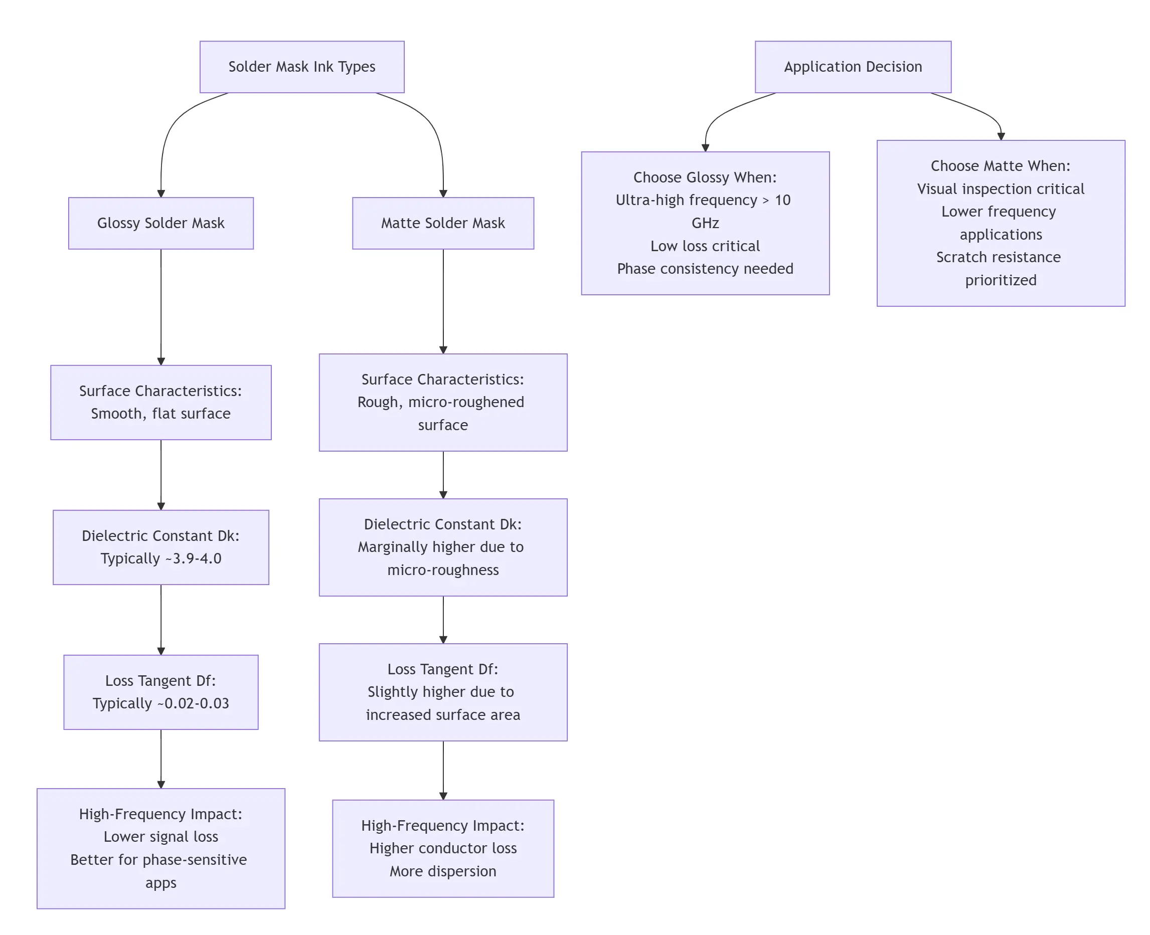
The dielectric constant (Dk or εr) and dissipation factor (Df or tanδ) are the two most important parameters when evaluating a solder mask's impact on electrical performance. While the typical Dk for standard solder masks (both matte and glossy) generally falls within the range of approximately 3.9 to 4.0, the key differences arise from their surface morphology.
-
Glossy Solder Masks cure to form a smooth, non-porous surface. This uniform structure results in a slightly lower and more stable dielectric constant because the dense cross-linking of polymers in the cured ink minimizes air gaps and other inhomogeneities that could affect the Dk.
-
Matte Solder Masks, in contrast, contain additives that create a microscopically rough surface. This roughness can introduce tiny air pockets. Since air has a Dk of about 1.0, these inclusions can slightly alter the effective Dk, often making it marginally different from its glossy counterpart. More critically, the increased surface area and potential for less dense polymer networks can lead to a higher dissipation factor (Df) for matte finishes compared to glossy ones of the same base formulation.
📡 Impact on High-Frequency Signals
At high frequencies, signal integrity is paramount. The primary concerns are insertion loss (weakening of the signal) and phase consistency.
-
Signal Loss Mechanisms:
-
Dielectric Loss: This is directly proportional to the Df of the material. A higher Df, as often seen in matte inks, means greater energy absorption and conversion to heat, leading to higher signal attenuation.
-
Conductor Loss: This becomes significantly pronounced due to the skin effect, where current flows predominantly on the conductor's surface at high frequencies. The rough surface of a matte solder mask increases the effective surface roughness of the underlying copper trace it covers. This forces the high-frequency current to travel a longer, more tortuous path, drastically increasing conductor loss. This effect often outweighs the minor differences in Dk.
-
-
Impedance and Phase Consistency:
-
The characteristic impedance of a transmission line depends on the effective Dk of the surrounding materials. A variation in Dk, or more likely, an inconsistent Dk due to non-uniform surface texture, can cause localized impedance mismatches. This leads to signal reflections and degradation.
-
Furthermore, the effective Dk is frequency-dependent. The different physical structures of matte and glossy finishes can cause this dispersion to behave slightly differently, affecting phase linearity.
-
📊 Practical Considerations for Selection
The choice between matte and glossy is a trade-off between electrical performance, reliability, and assembly needs.
-
Choose Glossy Solder Mask when:
-
Your design involves frequencies above 10 GHz or multi-gigabit serial links (>25 Gbps).
-
Lowest possible insertion loss is the top priority.
-
You require highly consistent phase response across a wide bandwidth.
-
-
Choose Matte Solder Mask when:
-
Operating frequencies are lower (e.g., below 5-10 GHz), where its impact on loss is less critical.
-
Visual inspection and touch-up during assembly are prioritized, as matte surfaces reduce glare.
-
Scratch resistance and ability to conceal handling marks are important.
-
💡 Mitigation Strategies
If you need the aesthetics of matte but are concerned about high-frequency performance, consider these approaches:
-
Consult Your PCB Fab House: Discuss your requirements with your manufacturer. They can provide measured data (Dk/Df) for their specific matte and glossy ink options and might have low-loss matte formulations.
-
Prioritize Low-Loss Materials: The choice of the underlying PCB laminate (e.g., low-loss "speed" grades) has a far greater impact on overall loss than the solder mask. Focus your budget and attention there first.
-
Review Vendor Datasheets: Always request the manufacturer's most recent datasheet for the specific solder mask product, which should include Dk and Df values at various frequencies (e.g., 1 GHz, 10 GHz).
✅ Conclusion
To summarize, while both matte and glossy solder masks have similar dielectric constants, the micro-roughness of matte finishes typically leads to a higher dissipation factor and significantly increased conductor loss at high frequencies due to the skin effect. For applications where signal integrity is the absolute priority, glossy solder mask is the superior choice. For many applications where aesthetics and handling are key, and frequencies are moderate, matte remains a viable option, but its impact on loss should be factored into your signal budget.
I hope this detailed explanation assists you in making an informed decision for your PCB design. If you have specific frequency and loss requirements, feel free to share for a more tailored discussion.