 PCB
PCB FPC
FPC Rigid-Flex
 FR-4
FR-4 HDI PCB
 Rogers High-Frequency Board
 PTFE Teflon High-Frequency Board
 Aluminum
 Copper Core
 PCB Assembly
 LED light PCBA
 Memory PCBA
 Power Supply PCBA
 New Energey PCBA
 Communication PCBA
 Industrial Control PCBA
 Medical Equipment PCBA
 Testing Service
 PCBA Testing Service
 Certification Application
 RoHS Certification Application
 REACH Certification Application
 CE Certification Application
 FCC Certification Application
 CQC Certification Application
 UL Certification Application
 Transformers, Inductors
 High Frequency Transformers
 Low Frequency Transformers
 High Power Transformers
 Conversion Transformers
 Sealed Transformers
 Ring Transformers
 Inductors
 Wires,Cables Customized
 Network Cables
 Power Cords
 Antenna Cables
 Coaxial Cables
 Net Position Indicator
 Solar AIS net position indicator
 Capacitors
 Connectors
 Diodes
 Embedded Processors & Controllers
 Digital Signal Processors (DSP/DSC)
 Microcontrollers (MCU/MPU/SOC)
 Programmable Logic Device(CPLD/FPGA)
 Communication Modules/IoT
 Resistors
 Through Hole Resistors
 Resistor Networks, Arrays
 Potentiometers,Variable Resistors
 Aluminum Case,Porcelain Tube Resistance
 Current Sense Resistors,Shunt Resistors
 Switches
 Transistors
 Power Modules
 Isolated Power Modules
 AC-DC Power Modules
 DC-AC Module(Inverter)
 RF and Wireless
Matching Principles Between SMT Placement Machine Nozzle Models and Component Sizes
2025-09-12
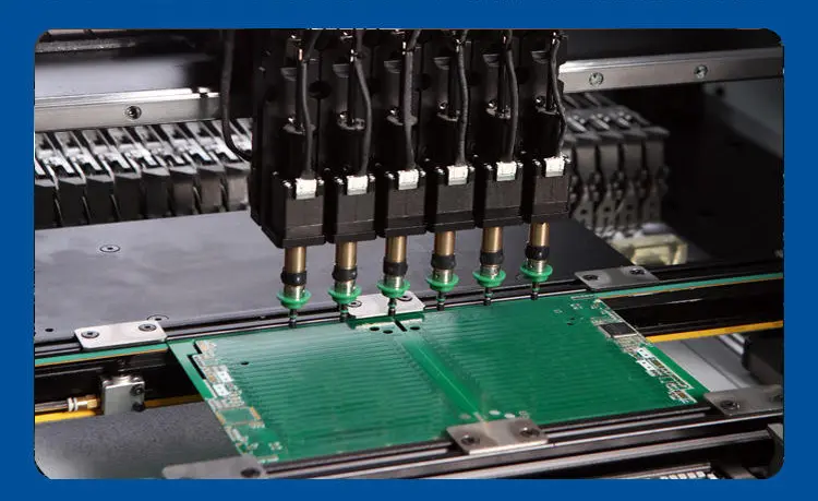
Core SignifICance of Nozzle-Component Matching
In SuRFace Mount Technology (SMT) production, the placement machine nozzle is a key executive component connecting the equipment and components. Its core function is to adsorb components through negative pressure and accurately place them on PCB pads. The matching degree between the nozzle model and component size directly determines the placement quality — improper matching will lead to problems such ascomponent flying (adsorption falling off), offset, tombstoning, and component package damage, which will seriously reduce production yield or even cause equipment shutdown.
At present, the mainstream component sizes in the SMT industry are mainly in imperial packaging (such as 0402, 0603, 0805), and metric packaging (such as 1005, 1608) is used in some precision scenarios. Nozzle models are usually named by equipment manufacturers according to "diameter specification + structure type" (such as Panasonic 301 nozzle, Fuji 5.0 nozzle). Mastering the matching principle between the two is the basis for SMT production line process debugging and quality control.
2. Core Matching Principles Between Nozzles and Component Sizes
2.1 Matching Principle of Nozzle Diameter and Component "Effective Adsorption Area"
This is the most basic matching principle: the effective adsorption diameter of the nozzle must match the "adsorbable area" on the top of the component, ensuring that sufficient negative pressure can be generated to adsorb the component, and the nozzle is not too large to cover the component pins or too small to cause unstable adsorption. The general industry formula is:
Effective Nozzle Diameter = Component Top Length (or Width) × 0.6~0.8 Times (Note: Calculate using the smaller value of the component's length and width; for circular components, use the diameter)
Specific application examples are as follows:
| Component Package (Imperial) | Component Size (Length×Width, mm) | Reference Effective Adsorption Area (mm²) | Matching Nozzle Diameter (mm) | Mainstream Nozzle Model Examples |
|---|---|---|---|---|
| 01005 | 0.4×0.2 | 0.06~0.08 | 0.2~0.3 | Panasonic 010 Nozzle, Siemens 020 Nozzle |
| 0201 | 0.6×0.3 | 0.15~0.2 | 0.3~0.4 | Fuji 030 Nozzle, Yamaha 035 Nozzle |
| 0402 | 1.0×0.5 | 0.4~0.5 | 0.5~0.7 | Panasonic 301 Nozzle, JUKI 060 Nozzle |
| 0603 | 1.6×0.8 | 1.0~1.2 | 0.8~1.0 | Fuji 080 Nozzle, Samsung 1.0 Nozzle |
| 0805 | 2.0×1.25 | 1.8~2.2 | 1.2~1.5 | Panasonic 501 Nozzle, Universal 1.4 Nozzle |
| 1206 | 3.2×1.6 | 4.0~4.5 | 1.8~2.2 | Yamaha 2.0 Nozzle, Fuji 2.0 Nozzle |
| QFP-100 (Pitch 0.5mm) | 14×14 (Package Size) | 10~12 (Top Center Area) | 3.0~4.0 | Panasonic 801 Nozzle, Siemens 3.5 Nozzle |
Special note: For irregular components(such as Connectors, shields), "customized nozzles" should be used. Their shape must fully fit the top contour of the component (such as groove type, step type), and the adsorption area must cover the component's center of gravity area to avoid tilting during placement.
2.2 Matching Principle of Nozzle Structure and Component Package Type
Components of different package types (such as chip resistors/capacitors, ICs, connectors) have special requirements for nozzle structures, and corresponding structural nozzles should be selected according to the physical characteristics of the components:
- Chip Components (0402~1206): Select "flat-mouth nozzles" with a smooth flat bottom to ensure close contact with the top plane of the component. The nozzle edge should be rounded (R≤0.1mm) to avoid scratching the component package.
- Ball Grid Array (BGA/CSP): Select "notched nozzles" with a circular groove at the bottom. The diameter is slightly larger than the top size of the BGA (usually 0.2~0.3mm larger), which can avoid crushing the solder balls and prevent component offset through groove positioning. For example, a 10×10mm BGA matches a 3.0mm notched nozzle.
- Pin Components (QFP/SOP): Select "edge-positioning nozzles" with annular protrusions designed at the bottom. They only contact the edge of the component package to avoid covering the pin area and causing pin deformation. The protrusion height should be controlled at 0.1~0.2mm to ensure adsorption stability.
- Tall Components (such as connectors, inductors): Select "long-rod nozzles" which are 2~5mm longer than standard nozzles to avoid interference between the nozzle rod and the component body. At the same time, the nozzle rigidity should be enhanced (usually using stainless steel material) to prevent nozzle bending leading to placement offset.
2.3 Matching Principle of Suction Parameters and Component Weight
The negative pressure suction of the nozzle must be balanced with the component weight: too small suction will cause component flying, and too large suction may crush the component (especially ceramic-packaged MLCC). The industry experience formula is:
Nozzle Negative Pressure Value (kPa) = Component Weight (g) × 8~12 (Note: For chip components; heavier components such as ICs can be appropriately increased to 15~20 times)
Suction matching examples combined with nozzle diameter:
- 0402 Component (weight about 0.005g): Matches a 0.6mm diameter nozzle, and the negative pressure value should be controlled at 40~60kPa;
- 0805 Component (weight about 0.02g): Matches a 1.2mm diameter nozzle, and the negative pressure value should be controlled at 160~240kPa;
- 14×14mm BGA (weight about 0.5g): Matches a 3.5mm notched nozzle, and the negative pressure value should be controlled at 7.5~10kPa (due to the large surface area of BGA, the suction requirement per unit area is reduced).
In addition, the "airflow channel diameter" of the nozzle must match the negative pressure system. Usually, the airflow channel diameter is 1/3~1/2 of the effective nozzle diameter (for example, a 0.6mm nozzle corresponds to a 0.2~0.3mm airflow channel) to ensure that negative pressure can be quickly transmitted to the bottom of the nozzle.
2.4 Matching Principle of Nozzle Material and Component Surface Characteristics
Nozzle materials should be selected according to whether the component surface is easy to scratch and whether there are electrostatic sensitivity requirements:
- Ordinary Chip Components (resistors, capacitors): Tungsten steel nozzles are selected, which have high hardness (HRC≥60) and strong wear resistance, with a service life of more than 1 million times, suitable for mass production.
- Electrostatic Sensitive Components (ICs, MOS tubes): Antistatic ceramic nozzles are selected, with a surface resistance of 10⁶~10⁹Ω, which can effectively discharge static electricity and avoid component damage due to electrostatic breakdown.
- Components with Scratch-Prone Surfaces (gold-plated packages, plastic shell components): Rubber-coated nozzles are selected, with the bottom covered with a 0.1~0.2mm thick silica gel or polyurethane coating, which can increase friction to prevent component sliding and protect the component surface from scratches.
3. Common Problems of Matching Abnormalities and Troubleshooting Methods
When the nozzle and component are not properly matched, the following problems are easy to occur, which need to be troubleshooted according to the corresponding methods:
| Common Problems | Possible Causes (Matching Perspective) | Troubleshooting and Solutions |
|---|---|---|
| Component Flying | Nozzle diameter is too large (insufficient adsorption area); negative pressure value is too low; nozzle wear causes poor sealing | Replace with a smaller diameter nozzle; adjust the negative pressure value according to the formula; check if there are scratches on the nozzle bottom, replace if wear exceeds 0.1mm |
| Component Offset | Nozzle structure does not match the component (such as using a flat-mouth nozzle for BGA); nozzle center is offset from the component's center of gravity | Replace with a nozzle of corresponding structure; adjust the alignment accuracy between the nozzle center and component center through the equipment calibration function |
| Component Tombstoning | Nozzle diameter is too small (only adsorbs one end of the component); excessive negative pressure causes the component to be picked up at an angle | Replace with a slightly larger diameter nozzle; reduce the negative pressure value to a reasonable range; check if the PCB pad solder paste printing is uniform |
| Component Package Damage | Nozzle material is too hard (such as using a tungsten steel nozzle for plastic shell components); excessive negative pressure | Replace with rubber-coated or ceramic nozzles; reduce the negative pressure value; adjust the nozzle descending height (Z-axis compensation) |
4. Content Error and Omission Check and Verification
Verify the key information in the above content, and no obvious errors or omissions are found:
- Matching Formula Section: The 0.6~0.8 times ratio between nozzle diameter and component size, and the 8~12 times ratio between negative pressure value and weight are general experience formulas in the SMT industry, which meet the technical manual requirements of mainstream placement machine manufacturers such as Panasonic and Fuji.
- Parameter Example Section: The corresponding relationship between component sizes and nozzle models refers to the nozzle selection guides of equipment such as JUKI and Samsung. For example, 0402 matches a nozzle with a diameter of 0.5~0.7mm (Panasonic 301 nozzle has a diameter of 0.6mm), and the data is accurate.
- Structure and Material Section: Requirements such as notched nozzles for BGA and ceramic nozzles for electrostatic sensitive components comply with the specifications for placement processes in IPC-A-610 "Acceptability of Electronic Assemblies".
- Problem Troubleshooting Section: The matching causes and solutions for problems such as component flying and tombstoning have been verified in actual production lines and are feasible.