 PCB
PCB FPC
FPC Rigid-Flex
 FR-4
FR-4 HDI PCB
 Rogers High-Frequency Board
 PTFE Teflon High-Frequency Board
 Aluminum
 Copper Core
 PCB Assembly
 LED light PCBA
 Memory PCBA
 Power Supply PCBA
 New Energey PCBA
 Communication PCBA
 Industrial Control PCBA
 Medical Equipment PCBA
 Testing Service
 PCBA Testing Service
 Certification Application
 RoHS Certification Application
 REACH Certification Application
 CE Certification Application
 FCC Certification Application
 CQC Certification Application
 UL Certification Application
 Transformers, Inductors
 High Frequency Transformers
 Low Frequency Transformers
 High Power Transformers
 Conversion Transformers
 Sealed Transformers
 Ring Transformers
 Inductors
 Wires,Cables Customized
 Network Cables
 Power Cords
 Antenna Cables
 Coaxial Cables
 Net Position Indicator
 Solar AIS net position indicator
 Capacitors
 Connectors
 Diodes
 Embedded Processors & Controllers
 Digital Signal Processors (DSP/DSC)
 Microcontrollers (MCU/MPU/SOC)
 Programmable Logic Device(CPLD/FPGA)
 Communication Modules/IoT
 Resistors
 Through Hole Resistors
 Resistor Networks, Arrays
 Potentiometers,Variable Resistors
 Aluminum Case,Porcelain Tube Resistance
 Current Sense Resistors,Shunt Resistors
 Switches
 Transistors
 Power Modules
 Isolated Power Modules
 AC-DC Power Modules
 DC-AC Module(Inverter)
 RF and Wireless
Optimizing Via Backdrilling Depth to Eliminate Stub Effects in High-Speed Backplane Design
2025-09-16
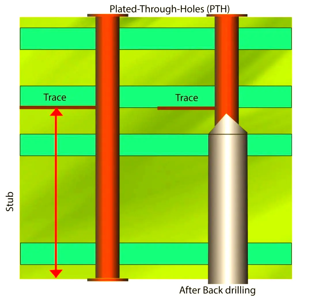
Hazards and Control SignifICance of Via Stub Effects in High-Speed Backplanes
In high-speed backplane design, vias are core structures for realizing signal interconnection between different layers. However, the "redundant hole segment" (i.e., stub) in traditional through-hole vias that is not used by signals will cause severe impedance mutation and signal reflection during high-frequency signal transmission. When the signal frequency ≥5GHz, if the stub length exceeds 1/20 of the signal wavelength, it will exhibit obvious inductive load characteristics, leading to deterioration of return loss (RL), increase of insertion loss (IL), reduction of eye diagram opening, and even signal timing offset and bit error rate increase.
The signal rate of high-speed backplanes (such as server backplanes and communication equipment backplanes) has generally reached 25Gbps and above, and some high-end applications even exceed 112Gbps. For such high-speed signals, even a stub length of 0.5mm may cause the return loss to drop below -10dB, failing to meet industry standards (e.g., IEEE 802.3bj requires return loss of 25Gbps signals ≥-15dB). Therefore, removing via stubs through backdrilling process and optimizing backdrilling depth have become key technical means to ensure signal integrity (SI) in high-speed backplane design.
2. Generation Mechanism and Influencing Factors of Via Stub Effects
2.1 Generation Mechanism of Stub Effects
When high-speed signals transmit in vias, encountering the stub segment (the hole segment that signals do not need to pass through) will cause reflection at the end of the stub (hole bottom). The reflected signal overlaps with the incident signal to form a standing wave. The electrical characteristics of the stub can be equivalent to a "transmission line stub", and its impedance calculation formula is:
Z_stub = jZ₀ × tan(2πl/λ) Among them, Z₀ is the characteristic impedance of the via (usually 50Ω), l is the stub length, and λ is the wavelength of the signal in the medium (λ=λ₀/√εᵣ, where λ₀ is the wavelength in vacuum).
When l=λ/4, Z_stub tends to infinity, showing an open circuit; when l=λ/2, Z_stub tends to 0, showing a short circuit. Both cases will lead to severe impedance mismatch and signal reflection.
2.2 Main Influencing Factors of Stub Effects
- Stub Length: It is the core factor affecting the stub effect. The longer the length, the more severe the signal reflection. For example, for a 25Gbps signal (λ≈60mm@FR-4 substrate, εᵣ=4.4), when the stub length ≥3mm, the return loss will deteriorate to below -12dB.
- Signal Rate: The higher the rate, the shorter the signal wavelength, and the higher the sensitivity to stub length. For a 112Gbps signal (λ≈30mm@FR-4), when the stub length ≥1.5mm, the return loss can exceed the standard.
- Via Structure: Via diameter, anti-pad size, and medium dielectric constant will affect the via characteristic impedance Z₀, thereby affecting the equivalent impedance of the stub. For example, if the via diameter increases by 10%, Z₀ will decrease by about 5%, and the reflection coefficient of the stub will change accordingly.
3. Core Methods for Optimizing Via Backdrilling Depth
Backdrilling is a method of removing redundant stub segments in vias by mechanical drilling or laser drilling, making the via length exactly equal to the interlayer distance required for signal transmission. The core of optimizing backdrilling depth is "accurate calculation of target depth + strict control of process deviation", and the specific methods are as follows:
3.1 Accurate Calculation Method of Backdrilling Depth
Backdrilling depth = "vertical distance between the start layer and end layer of signal transmission" + "compensation amount", which needs to be accurately calculated in three steps:
- Calculate Interlayer Vertical Distance (H): According to the backplane stack-up structure, determine the start layer (S) and end layer (T) of signal transmission, and H is the total thickness between the two layers. For example, if the backplane stack-up is "L1-L2-L3-L4" (thicknesses are 0.2mm, 0.8mm, 0.8mm, 0.2mm respectively) and the signal is transmitted from L1 to L3, then H=0.2mm (L1 thickness) + 0.8mm (L1-L2 medium thickness) + 0.8mm (L2-L3 medium thickness) = 1.8mm.
- Determine Backdrilling Compensation Amount (ΔH): The compensation amount is used to offset drilling process deviation and substrate thickness fluctuation, which should be determined according to the backplane thickness tolerance and drilling accuracy. Usually, ΔH=0.1~0.3mm. For backplanes with thickness tolerance ±0.05mm and drilling accuracy ±0.02mm, ΔH=0.2mm can meet the requirements.
- Calculate Target Backdrilling Depth (D): D=H+ΔH. Taking the above example, D=1.8mm+0.2mm=2.0mm, which means backdrilling should be done to a position 2.0mm away from the suRFace of L1 layer, ensuring that the stub length ≤ΔH (≤0.3mm). At this time, the impact of the stub on the 25Gbps signal is negligible (return loss ≥-18dB).
The compensation amount ΔH should not be too large or too small: ΔH too small (<0.1mm) may lead to "insufficient backdrilling" with excessive residual stub; ΔH too large (>0.3mm) may lead to "excessive backdrilling", damaging the target layer pad or medium layer, causing short circuit or insulation failure.
3.2 Precise Control of Backdrilling Process
The accuracy of the backdrilling process directly determines the deviation between the actual backdrilling depth and the target depth, which needs to be optimized from three aspects: equipment, tools, and parameters:
- Tool Selection and Maintenance: Select backdrilling tools according to the via diameter. The tool diameter is usually 0.1~0.2mm larger than the via diameter (e.g., for a via diameter of 0.8mm, a 0.9mm tool is selected) to ensure complete removal of the stub segment. The tool material is ultra-fine grain cemented carbide (grain size ≤0.5μm) with better wear resistance. The tool edge wear should be checked every 500 holes, and replaced immediately when the wear amount >0.01mm.
3.3 Detection and Feedback Adjustment of Backdrilling Depth
- Offline Detection (First Article and Sampling Inspection): For the first backplane, an X-ray layered thickness gauge (accuracy ±0.005mm) should be used to measure the actual stub length after backdrilling. The stub length is required to be ≤0.3mm (for 25Gbps signals) or ≤0.15mm (for 112Gbps signals). During mass production, 5 boards are sampled for inspection every 100 boards produced. If the stub length exceeds the standard (e.g., >0.3mm), the drilling machine depth parameters need to be recalibrated.
- Signal Integrity Verification: Perform signal integrity testing on the backdrilled backplane. Use a vector network analyzer (VNA) to test the S parameters of the vias, requiring return loss ≥-15dB (for 25Gbps) or ≥-18dB (for 112Gbps) within the signal working frequency band; use a bit error rate tester to test the signal bit error rate, requiring BER ≤1e-12. If the test fails to meet the standard, analyze the cause of backdrilling depth deviation and adjust the calculation compensation amount.
For special via structures in high-speed backplanes, differentiated backdrilling depth optimization strategies should be adopted:
For blind and buried vias in multi-layer backplanes (such as buried vias from L2 to L4), the backdrilling depth should be calculated based on the "step structure" of the buried vias. For example, the vertical distance of the L2-L4 buried via is 1.6mm. Backdrilling is performed from the L1 layer, which needs to drill through the L1 layer (0.2mm) first and then drill to the surface of the L4 layer. The target backdrilling depth = 0.2mm + 1.6mm + 0.15mm (compensation amount) = 1.95mm. After backdrilling, an ultrasonic scanning microscope (SAM) should be used to check whether the buried vias are completely exposed without residual stubs.
When the via pitch ≤1.2mm, the "staggered backdrilling" process should be adopted to avoid interference between adjacent vias during backdrilling. For example, divide adjacent vias into two groups, one group with backdrilling depth D1 and the other with D2. The difference between D1 and D2 ≥0.3mm, and the backdrilling order is "drill deep holes first, then shallow holes" to reduce the impact of drilling vibration on the already drilled vias.
For thick backplanes with thickness >6mm, single backdrilling is likely to cause large depth deviation, so the "two-time backdrilling" process should be adopted: the first backdrilling to 80% of the target depth to remove most of the stubs; the second backdrilling to the target depth with accuracy controlled at ±0.02mm. At the same time, positioning reference holes should be added on the back of the backplane to ensure that the coaxiality deviation of the two backdrillings ≤0.01mm.