 PCB
PCB FPC
FPC Rigid-Flex
 FR-4
FR-4 HDI PCB
 Rogers High-Frequency Board
 PTFE Teflon High-Frequency Board
 Aluminum
 Copper Core
 PCB Assembly
 LED light PCBA
 Memory PCBA
 Power Supply PCBA
 New Energey PCBA
 Communication PCBA
 Industrial Control PCBA
 Medical Equipment PCBA
 Testing Service
 PCBA Testing Service
 Certification Application
 RoHS Certification Application
 REACH Certification Application
 CE Certification Application
 FCC Certification Application
 CQC Certification Application
 UL Certification Application
 Transformers, Inductors
 High Frequency Transformers
 Low Frequency Transformers
 High Power Transformers
 Conversion Transformers
 Sealed Transformers
 Ring Transformers
 Inductors
 Wires,Cables Customized
 Network Cables
 Power Cords
 Antenna Cables
 Coaxial Cables
 Net Position Indicator
 Solar AIS net position indicator
 Capacitors
 Connectors
 Diodes
 Embedded Processors & Controllers
 Digital Signal Processors (DSP/DSC)
 Microcontrollers (MCU/MPU/SOC)
 Programmable Logic Device(CPLD/FPGA)
 Communication Modules/IoT
 Resistors
 Through Hole Resistors
 Resistor Networks, Arrays
 Potentiometers,Variable Resistors
 Aluminum Case,Porcelain Tube Resistance
 Current Sense Resistors,Shunt Resistors
 Switches
 Transistors
 Power Modules
 Isolated Power Modules
 AC-DC Power Modules
 DC-AC Module(Inverter)
 RF and Wireless
Impact of Grid Ground vs. Solid Ground on Flexibility Performance in Flexible PCB (FPC) Grounding Design
2025-11-07
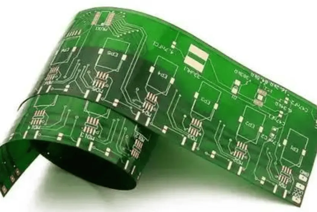
Flexible printed circuits (FPCs) are indispensable in electronic devices requiring mechanical flexibility—such as foldable smartphones, wearable tech, and automotive sensors—where grounding design must balance electrical peRFormance and bending reliability. Grid ground and solid ground are two primary grounding schemes in FPCs, each with distinct structural characteristics that directly influence the board’s ability to withstand repeated bending without failure. This article details the specific impacts of these two grounding methods on FPC bending performance, drawing on mechanical testing data, material science principles, and industry design practices.
1. Structural Differences: Grid Ground vs. Solid Ground
The core distinction between the two grounding schemes lies in their copper layer configuration, which lays the foundation for their differing bending behaviors:
- Solid ground: Consists of a continuous, unbroken copper foil layer (typically 18–35μm thick) covering a designated area of the FPC. It acts as a comprehensive ground plane, providing low impedance for signal return and electromagnetic interference (EMI) shielding. The continuous copper structure offers high structural rigidity but limited flexibility.
- Grid ground: Features a copper layer etched into a grid pattern—comprising parallel and perpendicular copper traces (width: 0.2–0.5mm, pitch: 1–3mm) forming interconnected squares or rectangles. The grid retains grounding functionality (via overlapping conductive paths) while introducing gaps (typically 70–90% open area) that reduce the overall copper coverage and rigidity.
2. Key Impacts on Bending Performance
Bending performance is evaluated by three critical metrics: bending fatigue life (number of cycles before failure), minimum bend radius, and stress distribution during bending. The following analysis quantifies the differences between grid and solid ground:
2.1 Bending Fatigue Life: Grid Ground Extends Durability
Repeated bending causes cyclic stress in the FPC’s copper layer, leading to fatigue cracks and eventual wire breakage. Test data for standard FPCs (18μm copper, PI substrate, 0.1mm total thickness) shows:
- Solid ground: Fatigue life ranges from 10,000–50,000 bending cycles (180° dynamic bending, 1mm radius). The continuous copper layer accumulates concentrated stress at the bending interface, with cracks typically forming within 30,000 cycles for dynamic applications (e.g., foldable phone hinges).
- Grid ground: Fatigue life increases to 50,000–200,000 cycles under the same conditions. The grid’s open structure dissipates stress across diSCRete trace segments, reducing localized strain. For example, a grid with 0.3mm trace width and 2mm pitch achieves 150,000+ cycles—3x longer than solid ground.
- Extreme bending scenarios: In ultra-small bend radius (0.5mm) tests, solid ground fails within 5,000 cycles, while grid ground maintains functionality for 30,000+ cycles. The gaps in the grid allow the substrate to flex more freely, minimizing tensile stress on copper traces.
2.2 Minimum Bend Radius: Grid Ground Enables Tighter Bends
The minimum bend radius (the smallest radius an FPC can withstand without permanent damage) is a key indicator of flexibility:
- Solid ground: Requires a minimum bend radius of 5–8x the FPC thickness. For a 0.2mm thick FPC, this translates to 1–1.6mm. Bending beyond this radius causes immediate copper delamination or cracking due to excessive strain (exceeding copper’s elongation at break of 15–20%).
- Grid ground: Reduces the minimum bend radius to 2–4x the FPC thickness. The same 0.2mm FPC can bend to 0.4–0.8mm—50% smaller than solid ground. The grid’s segmented structure allows individual copper traces to flex independently, avoiding the rigid constraints of a continuous layer.
2.3 Stress Distribution: Grid Ground Reduces Localized Strain
During bending, stress concentrates on the outer arc of the FPC. Finite element analysis (FEA) simulations reveal:
- Solid ground: Stress is uniformly high (150–200MPa) across the entire outer copper layer, exceeding the fatigue limit of copper (≈100MPa) after repeated cycles. This leads to rapid crack propagation along the bending axis.
- Grid ground: Stress is distributed across the grid’s trace intersections, with peak stress reduced to 80–120MPa. The open gaps act as stress relief zones, preventing concentrated strain buildup. For transverse bending (perpendicular to grid traces), stress is further reduced by 30% compared to solid ground.
3. Factors Modifying the Impact Magnitude
The performance gap between grid and solid ground is not fixed; it is influenced by three key design and material factors:
3.1 Grid Design Parameters
- Trace width and pitch: Narrower traces (0.2mm) and larger pitches (3mm) enhance flexibility but may reduce grounding efficiency. A balance (0.3mm width, 2mm pitch) optimizes both bending performance and electrical conductivity.
- Grid orientation: Aligning grid traces parallel to the primary bending axis reduces stress by 20% compared to transverse alignment, as traces flex along their length rather than across their width.
3.2 Copper Thickness
- Thicker copper (35μm) exacerbates the rigidity of solid ground, reducing fatigue life by 40% compared to 18μm copper. For grid ground, thicker copper has a smaller impact—fatigue life decreases by only 15%, as the grid structure mitigates stress concentration.
3.3 Substrate Material
- PI (polyimide) substrates, with higher flexibility (elongation at break: 200–300%) than PET (100–150%), amplify the performance advantage of grid ground. In PI-based FPCs, grid ground outperforms solid ground by 40% in fatigue life, compared to 25% in PET-based FPCs.
4. Trade-Offs: Electrical Performance vs. Bending Reliability
While grid ground superiorizes bending performance, it involves trade-offs in electrical functionality:
- Ground impedance: Grid ground has slightly higher impedance (5–10mΩ/sq) than solid ground (1–3mΩ/sq) due to reduced copper coverage. This is negligible for low-frequency signals but may require optimization (e.g., smaller pitch) for high-frequency (>1GHz) applications.
- EMI shielding: Solid ground provides 20–30dB better EMI shielding than grid ground, as the continuous copper layer blocks electromagnetic radiation more effectively. For EMI-sensitive devices, a hybrid design (grid ground in bending areas, solid ground in static regions) is recommended.
- Heat dissipation: Solid ground dissipates heat 30–50% more efficiently than grid ground. For high-power FPCs (>2W), combining grid ground with thermal vias can mitigate this limitation.
5. Practical Design Guidelines
To balance bending performance and electrical functionality, follow these industry best practices:
- Use grid ground in dynamic bending areas (e.g., hinges, connectors) where fatigue life and tight bend radii are critical. Opt for a 0.3mm trace width, 2mm pitch, and align traces parallel to the bending axis.
- Reserve solid ground for static regions (e.g., component mounting areas) to maintain low impedance and EMI shielding.
- For hybrid designs, transition smoothly between grid and solid ground with tapered traces to avoid stress concentration at the interface.
- For ultra-flexible applications (e.g., wearable sensors), use double-sided grid ground with staggered traces to enhance flexibility while maintaining grounding continuity.
In FPC grounding design, grid ground significantly outperforms solid ground in bending performance—extending fatigue life by 2–3x, enabling 50% smaller minimum bend radii, and reducing localized stress by 30–40%. The core advantage stems from the grid’s segmented structure, which dissipates stress and allows the substrate to flex freely. While grid ground involves minor trade-offs in impedance and EMI shielding, these can be mitigated through optimized grid parameters or hybrid designs. For applications requiring repeated bending or tight form factors, grid ground is the preferred choice, while solid ground remains suitable for static, EMI-sensitive regions. By aligning grounding scheme selection with the FPC’s mechanical requirements, designers can maximize both reliability and performance.