 PCB
PCB FPC
FPC Rigid-Flex
 FR-4
FR-4 HDI PCB
 Rogers High-Frequency Board
 PTFE Teflon High-Frequency Board
 Aluminum
 Copper Core
 PCB Assembly
 LED light PCBA
 Memory PCBA
 Power Supply PCBA
 New Energey PCBA
 Communication PCBA
 Industrial Control PCBA
 Medical Equipment PCBA
 Testing Service
 PCBA Testing Service
 Certification Application
 RoHS Certification Application
 REACH Certification Application
 CE Certification Application
 FCC Certification Application
 CQC Certification Application
 UL Certification Application
 Transformers, Inductors
 High Frequency Transformers
 Low Frequency Transformers
 High Power Transformers
 Conversion Transformers
 Sealed Transformers
 Ring Transformers
 Inductors
 Wires,Cables Customized
 Network Cables
 Power Cords
 Antenna Cables
 Coaxial Cables
 Net Position Indicator
 Solar AIS net position indicator
 Capacitors
 Connectors
 Diodes
 Embedded Processors & Controllers
 Digital Signal Processors (DSP/DSC)
 Microcontrollers (MCU/MPU/SOC)
 Programmable Logic Device(CPLD/FPGA)
 Communication Modules/IoT
 Resistors
 Through Hole Resistors
 Resistor Networks, Arrays
 Potentiometers,Variable Resistors
 Aluminum Case,Porcelain Tube Resistance
 Current Sense Resistors,Shunt Resistors
 Switches
 Transistors
 Power Modules
 Isolated Power Modules
 AC-DC Power Modules
 DC-AC Module(Inverter)
 RF and Wireless
 News Categories
Drill Bit Selection to Reduce Substrate Tearing When Drilling Flexible Regions of Rigid-Flex PCBs
2025-10-22
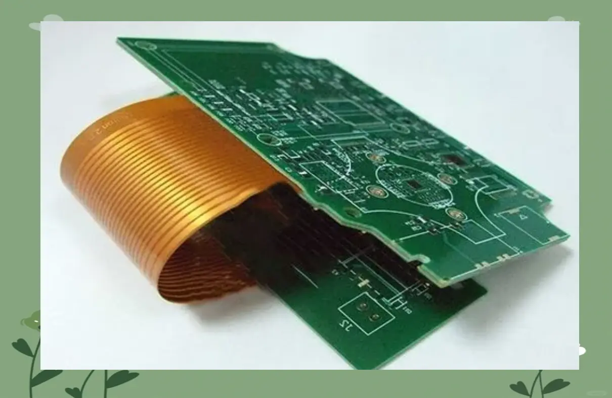
Rigid-Flex Pcbs combine rigid FR-4 sections (for component mounting) and flexible polyimide (PI) or polyester (PET) regions (for bending and dynamic applications), making them ideal for compact, space-constrained devices like wearable electronics, automotive sensors, and medical implants. Drilling the flexible regions—typically composed of thin PI layers (25–125μm) reinforced with glass fiber or aramid fibers—poses unique challenges not seen in Rigid Pcb drilling.
The primary defect in flexible region drilling is substrate tearing, which manifests as:
- Delamination: Separation of PI layers or between PI and adhesive films.
- Fiber pull-out: Glass/aramid fibers in the flexible substrate are torn or pulled from the resin matrix.
- Edge fraying: Ragged, uneven drill hole edges that compromise mechanical flexibility and electrical insulation.
Tearing occurs because flexible substrates have low tensile strength (PI: 150–200MPa vs. FR-4: 200–300MPa) and poor resistance to shear forces. Conventional drill bits designed for rigid FR-4 often apply excessive point pressure or generate uneven cutting forces, exacerbating tearing. Selecting the right drill bit type is critical to reducing tearing rates from 15–20% (with standard bits) to <2%.
2. Key Properties of Flexible Substrates Affecting Drill Bit Performance
To identify optimal drill bits, it is first necessary to understand the material characteristics of rigid-flex flexible regions that influence drilling behavior:
| Flexible Substrate Type | Core Material | Mechanical Properties | Drilling Challenge |
|---|---|---|---|
| PI-Based Flexible | Polyimide (PI) + glass/aramid reinforcement | Low shear strength (50–70MPa), high flexibility (elongation at break: 50–80%) | PI adheres to drill bits; reinforcement fibers resist cutting, causing tearing. |
| PET-Based Flexible | Polyester (PET) + thin copper | Lower thermal resistance (Tg: 70–80℃), brittle compared to PI | Heat from drilling softens PET, leading to melted edges and tearing. |
| Adhesive-Layered | PI + acrylic adhesive | Low bond strength between layers (5–10N/cm) | Drill pressure easily separates layers, causing delamination. |
Flexible regions also often have thinner copper foils (12–35μm) than rigid sections, requiring drill bits that minimize copper burring while avoiding substrate damage.
3. Optimal Drill Bit Types for Flexible Region Drilling
Not all drill bits are suitable for flexible substrates. Below is a comparison of drill bit types, their performance in flexible regions, and recommended applications:
3.1 Spiral-Flute Drill Bits with Rounded Point Angles (Top Recommendation)
Design Features:
- Point angle: 130–140° (rounded, not sharp), which distributes cutting force over a wider area.
- Flute geometry: 2–3 spiral flutes with a high helix angle (40–45°) to improve chip evacuation and reduce PI adhesion.
- Material: Tungsten carbide (WC) with diamond-like carbon (DLC) coating—low friction (coefficient of friction: 0.1–0.15) prevents PI from sticking to the bit.
Performance:
- Reduces tearing by 70–80% compared to standard bits. The rounded point minimizes point pressure, while the DLC coating prevents PI buildup.
- Ideal for PI-based flexible regions (the most common type in rigid-flex PCBs).
Application Example: A 0.3mm diameter spiral-flute drill bit (135° point, DLC coating) drilling 50μm PI + 25μm glass fiber flexible regions achieves a tearing rate of <1.5%.
3.2 Brad-Point Drill Bits (For Thin, Unreinforced Flexible Substrates)
Design Features:
- Point design: A sharp central brad (0.05–0.1mm diameter) that penetrates the substrate first, guiding the bit without wandering.
- Cutting edges: Two flat, sharp edges adjacent to the brad that shear the substrate rather than tearing it.
- Material: High-speed steel (HSS) or WC with titanium nitride (TiN) coating for wear resistance.
Performance:
- Excellent for thin, unreinforced PI/PET (25–50μm) with no glass fibers. The brad prevents bit walk, while shear cutting minimizes fraying.
- Less effective for reinforced substrates, as the brad can snag on glass fibers.
Limitation: Higher risk of copper burring on flexible regions with copper layers; requires post-drilling deburring.
3.3 Step-Drill Bits (For Large-Diameter Holes in Flexible Regions)
Design Features:
- Multi-step geometry: Conical steps that gradually increase in diameter (e.g., 0.2mm → 0.4mm → 0.6mm), reducing incremental cutting force.
- Flute count: 3–4 flutes for enhanced stability and chip removal.
Performance:
- Ideal for large holes (≥0.5mm) in flexible regions, where single-pass drilling with standard bits would apply excessive force. Step-wise cutting distributes stress, reducing delamination by 60–70%.
Application Example: A 0.6mm step-drill bit drilling a PI-based flexible region with 75μm thickness reduces tearing from 18% (standard bit) to 5%.
3.4 Avoid These Drill Bits for Flexible Regions
- Standard 118° Point Drill Bits: Sharp points concentrate pressure, causing immediate PI tearing and fiber pull-out.
- Twist Drill Bits with Low Helix Angles (<30°): Poor chip evacuation leads to PI buildup on the bit, increasing friction and tearing.
- HSS Uncoated Drill Bits: High friction causes PI adhesion and excessive heat, softening the substrate and exacerbating tearing.
4. Supplementary Drill Bit and Process Optimizations
Even with the right drill bit type, additional adjustments are needed to maximize tear reduction in flexible region drilling:
4.1 Drill Bit Coating Enhancements
- DLC vs. TiAlN Coatings: For PI substrates, DLC coatings are preferred (lower friction) over titanium aluminum nitride (TiAlN) coatings. DLC reduces PI adhesion by 50–60%, minimizing edge fraying.
- Nano-Ceramic Coatings: For reinforced flexible substrates (glass/aramid fibers), nano-ceramic coatings (e.g., Al₂O₃-TiO₂) improve wear resistance by 40%, maintaining sharp cutting edges longer and reducing tearing from dull bits.
4.2 Drill Bit Sizing Considerations
- Oversizing: For flexible regions, drill bits should be 0.01–0.02mm larger than the target hole diameter. This compensates for PI’s elastic recovery (PI shrinks slightly after drilling) and reduces compressive stress on the substrate.
- Shank Diameter: Use drill bits with a 1:1 shank-to-cutting diameter ratio (e.g., 0.3mm cutting diameter → 0.3mm shank) for better stability, minimizing vibration-induced tearing.
4.3 Drilling Process Parameters to Complement Bit Selection
- Drill Speed: 20,000–30,000 RPM for PI-based flexible regions. Higher speeds (vs. rigid FR-4) create cleaner, faster cuts, reducing substrate dwell time.
- Feed Rate: 15–30 mm/min (feed per revolution: 0.8–1.5 μm/rev). Low feed rates minimize shear force, while high rates risk tearing.
- Cooling: Use mist cooling (compressed air + 5–10 mL/hour of water-soluble lubricant) to reduce heat and prevent PI melting. Avoid liquid cooling, as it can seep into flexible layers and cause delamination.
5. Post-Drilling Inspection and Validation
To confirm drill bit effectiveness, implement these inspection steps for flexible region holes:
5.1 Visual Inspection
- Use a stereo microscope (magnification 50–100x) to check for:
- Tearing: Ragged edges, fiber pull-out, or delamination around the hole.
- Edge quality: Acceptable holes have smooth, even edges with no fraying (fray width ≤5μm).
- Reject flexible regions with tearing affecting >10% of the hole circumference.
5.2 Mechanical Flexibility Testing
- Subject drilled flexible regions to bend cycling (10,000 cycles at ±90° bending angle). Tear-free holes maintain structural integrity, while torn holes show progressive delamination after 1,000–2,000 cycles.
5.3 Electrical Insulation Testing
- Measure insulation resistance between adjacent holes using a 500V DC megohmmeter. Acceptable resistance is ≥10¹⁰Ω; lower values indicate tearing-induced insulation degradation.
6. Conclusion
Reducing substrate tearing when drilling flexible regions of rigid-flex PCBs hinges on selecting drill bits that match the substrate’s mechanical properties and drilling requirements. The optimal choices are:
- Primary choice: Spiral-flute drill bits with 130–140° rounded points and DLC coatings (for PI-based, reinforced flexible regions).
- Secondary choices: Brad-point bits (thin, unreinforced substrates) or step-drill bits (large-diameter holes).
Complemented by proper coatings (DLC/nano-ceramic), optimized speeds/feed rates (20,000–30,000 RPM + 15–30 mm/min), and mist cooling, these drill bits reduce tearing rates to <2%.