 PCB
PCB FPC
FPC Rigid-Flex
 FR-4
FR-4 HDI PCB
 Rogers High-Frequency Board
 PTFE Teflon High-Frequency Board
 Aluminum
 Copper Core
 PCB Assembly
 LED light PCBA
 Memory PCBA
 Power Supply PCBA
 New Energey PCBA
 Communication PCBA
 Industrial Control PCBA
 Medical Equipment PCBA
 Testing Service
 PCBA Testing Service
 Certification Application
 RoHS Certification Application
 REACH Certification Application
 CE Certification Application
 FCC Certification Application
 CQC Certification Application
 UL Certification Application
 Transformers, Inductors
 High Frequency Transformers
 Low Frequency Transformers
 High Power Transformers
 Conversion Transformers
 Sealed Transformers
 Ring Transformers
 Inductors
 Wires,Cables Customized
 Network Cables
 Power Cords
 Antenna Cables
 Coaxial Cables
 Net Position Indicator
 Solar AIS net position indicator
 Capacitors
 Connectors
 Diodes
 Embedded Processors & Controllers
 Digital Signal Processors (DSP/DSC)
 Microcontrollers (MCU/MPU/SOC)
 Programmable Logic Device(CPLD/FPGA)
 Communication Modules/IoT
 Resistors
 Through Hole Resistors
 Resistor Networks, Arrays
 Potentiometers,Variable Resistors
 Aluminum Case,Porcelain Tube Resistance
 Current Sense Resistors,Shunt Resistors
 Switches
 Transistors
 Power Modules
 Isolated Power Modules
 AC-DC Power Modules
 DC-AC Module(Inverter)
 RF and Wireless
Setting Drag Angle in Selective Wave Soldering to Prevent Bridging Defects
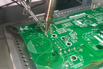
1. Mechanism of Bridging Defects
Bridging occurs when solder fails to separate between adjacent joints, primarily due to:
-
Excessive solder: Low drag angle prolongs solder contact time, inhibiting separation by suRFace tension;
-
Uneven wetting: Improper angle disrupts flux activity and solder flow;
-
Poor dynamIC separation: Angle-speed mismatch causes trailing residues.
2. Drag Angle Definition & Role
Drag angle (typically 3°–7°) between PCB and solder wave affects:
-
Contact time: Higher angles reduce solder volume;
-
Flow direction: Controls lateral spreading to prevent overflow;
-
Separation dynamics: Optimizes surface tension-driven separation.
3. Parameter Optimization
3.1 Angle Range
-
Standard: 4°–6° (general components), adjusted by:
-
Component density: 5°–7° for high-density areas (e.g., QFP leads);
-
Pad pitch: +1°–2° for pitches <0.5mm;
-
Solder type: Reduce 0.5°–1° for lead-free (SnAgCu) solder.
-
3.2 Parameter Synergy
-
Wave height: Lower angle with higher wave (2mm → 5°; 3mm → 4°);
-
Conveyor speed: Increase angle at higher speeds (1.2m/min → 6°; 1.5m/min → 6.5°);
-
Preheat temperature: +1° angle if preheat <90°C.
3.3 Dynamic Adjustments
-
Zoned angles: Set varying angles for different regions (e.g., 5° for BGA, 7° for Connectors);
-
Real-time feedback: Adjust angle (±0.5°) via IR thermography and AOI.
4. Validation Methods
-
DoE: Full factorial tests with angle (4°,5°,6°), speed (1.0–1.8m/min), wave height (1.5–2.5mm);
-
High-speed imaging: Quantify necking behavior during solder separation;
-
SPC: Monitor angle stability (CPK≥1.33) for batch consistency.
5. Typical Process Parameters
| Application | Drag Angle | Wave Height | Speed | Preheat |
|---|---|---|---|---|
| Through-hole (THT) | 5°–6° | 2.0mm | 1.2m/min | 100–110°C |
| Fine-pitch QFP (0.4mm) | 6.5°–7° | 1.8mm | 1.0m/min | 110–120°C |
| High-density BGA | 4.5°–5.5° | 2.2mm | 1.5m/min | 95–105°C |
6. Troubleshooting
-
Issue 1: Persistent bridging post-adjustment
Solution: Verify flux coverage (≥90%) and wave flatness (±0.1mm). -
Issue 2: Cold joints from angle-speed mismatch
Solution: Implement angle-speed correlation curves (+1° angle → -0.1m/min speed). -
Issue 3: Low efficiency in PCB changeovers
Solution: Preset parameter libraries with QR code auto-loading.