 PCB
PCB FPC
FPC Rigid-Flex
 FR-4
FR-4 HDI PCB
 Rogers High-Frequency Board
 PTFE Teflon High-Frequency Board
 Aluminum
 Copper Core
 PCB Assembly
 LED light PCBA
 Memory PCBA
 Power Supply PCBA
 New Energey PCBA
 Communication PCBA
 Industrial Control PCBA
 Medical Equipment PCBA
 Testing Service
 PCBA Testing Service
 Certification Application
 RoHS Certification Application
 REACH Certification Application
 CE Certification Application
 FCC Certification Application
 CQC Certification Application
 UL Certification Application
 Transformers, Inductors
 High Frequency Transformers
 Low Frequency Transformers
 High Power Transformers
 Conversion Transformers
 Sealed Transformers
 Ring Transformers
 Inductors
 Wires,Cables Customized
 Network Cables
 Power Cords
 Antenna Cables
 Coaxial Cables
 Net Position Indicator
 Solar AIS net position indicator
 Capacitors
 Connectors
 Diodes
 Embedded Processors & Controllers
 Digital Signal Processors (DSP/DSC)
 Microcontrollers (MCU/MPU/SOC)
 Programmable Logic Device(CPLD/FPGA)
 Communication Modules/IoT
 Resistors
 Through Hole Resistors
 Resistor Networks, Arrays
 Potentiometers,Variable Resistors
 Aluminum Case,Porcelain Tube Resistance
 Current Sense Resistors,Shunt Resistors
 Switches
 Transistors
 Power Modules
 Isolated Power Modules
 AC-DC Power Modules
 DC-AC Module(Inverter)
 RF and Wireless
Suppressing Dog-bone Effect in Ultra-high Aspect Ratio (>20:1) Through-hole Electroplating
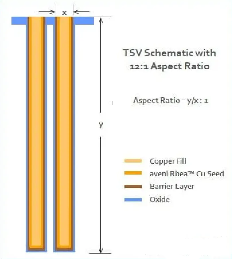
Dog-bone Effect refers to the phenomenon where the plating thICkness at the via entrance and exit is significantly greater than the middle region during high-aspect-ratio through-hole electroplating. This arises from limited electrolyte mass transfer and uneven current distribution. Below are strategies to suppress it:
1. Electrolyte Formulation Optimization
-
Additive Control:
-
Suppressors (e.g., PEG, imidazole derivatives) adsorb at high-current-density areas (via entrance) to slow deposition (20–30% reduction).
-
Accelerators (e.g., SPS) enhance metal ion reduction in low-current-density regions (via interior).
-
Levelers (e.g., Janus Green B) dynamically balance deposition rates.
-
Optimal Ratios: DoE-guided concentrations (e.g., PEG: 50–200 ppm, SPS: 5–20 ppm).
-
-
Electrolyte Parameters:
-
High CuSO₄ concentration (200–300 g/L) to improve mass transfer.
-
Low H₂SO₄ (10–50 g/L) and controlled Cl⁻ (50–100 ppm) for additive synergy.
-
2. Process Parameter Tuning
-
Current Modulation:
-
Pulse Reverse Plating (PRC): Forward current () with periodic reverse dissolution ().
-
Periodic Pulse Reversal (PPR) to redistribute ions.
-
-
Mass Transfer Enhancement:
-
Jet flow (>2 m/s) or ultrasonic agitation (20–40 kHz) to reduce diffusion layer thickness.
-
Temperature control (25–35°C).
-
-
Staged Plating: Initial low current () for bottom nucleation, followed by higher current ().
3. Equipment & Auxiliary Design
-
Auxiliary Anodes:
-
Micro IrO₂/Ti anodes near via bottoms to boost local current density by 10–20%.
-
-
Cathode Shielding:
-
Insulating masks at via entrances to reduce edge field concentration.
-
-
Rotating Cathode:
-
10–30 RPM rotation for uniform electrolyte penetration.
-
4. Via Pretreatment
-
Wall Activation:
-
Electroless Pd or sputtered Au layers to reduce inteRFacial resistance.
-
-
Surface Roughening:
-
Plasma etching or H₂SO₄-H₂O₂ micro-etching to enhance adhesion.
-
5. SIMulation & Monitoring
-
Multiphysics Modeling:
-
COMSOL-based current-mass transfer-deposition models to predict plating profiles.
-
-
In-situ Sensors:
-
Four-point probes for real-time thickness feedback.
-
6. Validation Metrics
-
Uniformity: FIB-SEM-measured thickness variation <10%.
-
Reliability: No cracks/delamination after 1000 thermal cycles (-55–125°C); resistance drift <5%.