 PCB
PCB FPC
FPC Rigid-Flex
 FR-4
FR-4 HDI PCB
 Rogers High-Frequency Board
 PTFE Teflon High-Frequency Board
 Aluminum
 Copper Core
 PCB Assembly
 LED light PCBA
 Memory PCBA
 Power Supply PCBA
 New Energey PCBA
 Communication PCBA
 Industrial Control PCBA
 Medical Equipment PCBA
 Testing Service
 PCBA Testing Service
 Certification Application
 RoHS Certification Application
 REACH Certification Application
 CE Certification Application
 FCC Certification Application
 CQC Certification Application
 UL Certification Application
 Transformers, Inductors
 High Frequency Transformers
 Low Frequency Transformers
 High Power Transformers
 Conversion Transformers
 Sealed Transformers
 Ring Transformers
 Inductors
 Wires,Cables Customized
 Network Cables
 Power Cords
 Antenna Cables
 Coaxial Cables
 Net Position Indicator
 Solar AIS net position indicator
 Capacitors
 Connectors
 Diodes
 Embedded Processors & Controllers
 Digital Signal Processors (DSP/DSC)
 Microcontrollers (MCU/MPU/SOC)
 Programmable Logic Device(CPLD/FPGA)
 Communication Modules/IoT
 Resistors
 Through Hole Resistors
 Resistor Networks, Arrays
 Potentiometers,Variable Resistors
 Aluminum Case,Porcelain Tube Resistance
 Current Sense Resistors,Shunt Resistors
 Switches
 Transistors
 Power Modules
 Isolated Power Modules
 AC-DC Power Modules
 DC-AC Module(Inverter)
 RF and Wireless
Detection Methods for SMT Component Polarity Errors: A Comprehensive Analysis
Abstract: Reversed installation of polarized components (Diodes, electrolytic capacitors) causes circuit failure, component burnout, or even explosions. Per IPC-A-610 and J-STD-001, detection requires a three-tier system:
-
Optical Inspection (silkSCReen/marking comparison)
-
Electrical Testing (reverse leakage/ESR)
-
X-ray Verification (internal structure check)
1. Optical Inspection: Silkscreen & Marking Comparison
-
Polarity Marking Rules:
Component Anode Marking Cathode Marking Tools Diode Unmarked Band/Stripe AOI (0.01mm res.) Electrolytic Cap Long lead/"+" symbol Short lead/black "-" 20× magnifier Tantalum Cap Solid bar Unmarked side 3D SPI (height check) -
AOI Programming:
-
Feature Extraction:
-
Diode cathode band: Grayscale contrast threshold >60%
-
Cap polarity symbol: OCR accuracy ≥99.5%
-
-
Logic:
if component.type == "Diode": if cathode_band_position != design_db_position: raise PolarityError
-
2. Electrical Testing: Static Parameter Validation
-
Diode Reverse Test:
Condition Class 3 Standard Failure Sign 5V Reverse Voltage Leakage ≤0.1μA >1μA (possible breakdown) 1mA Forward Bias 0.5–0.7V (Si diode) >1V (possible open) -
Capacitor ESR Test:
-
Electrolytic cap (100μF/16V): ESR ≤1.5Ω@100kHz
-
Reversed caps show 3–5× higher ESR (e.g., reversed tantalum ESR>10Ω)
-
-
In-Circuit Test (ICT):
-
Apply 5V reverse bias across diode test points; alarm if current exceeds limit;
-
Impedance-Phase Angle Test (LCR meter): Phase shift >20° when reversed.
-
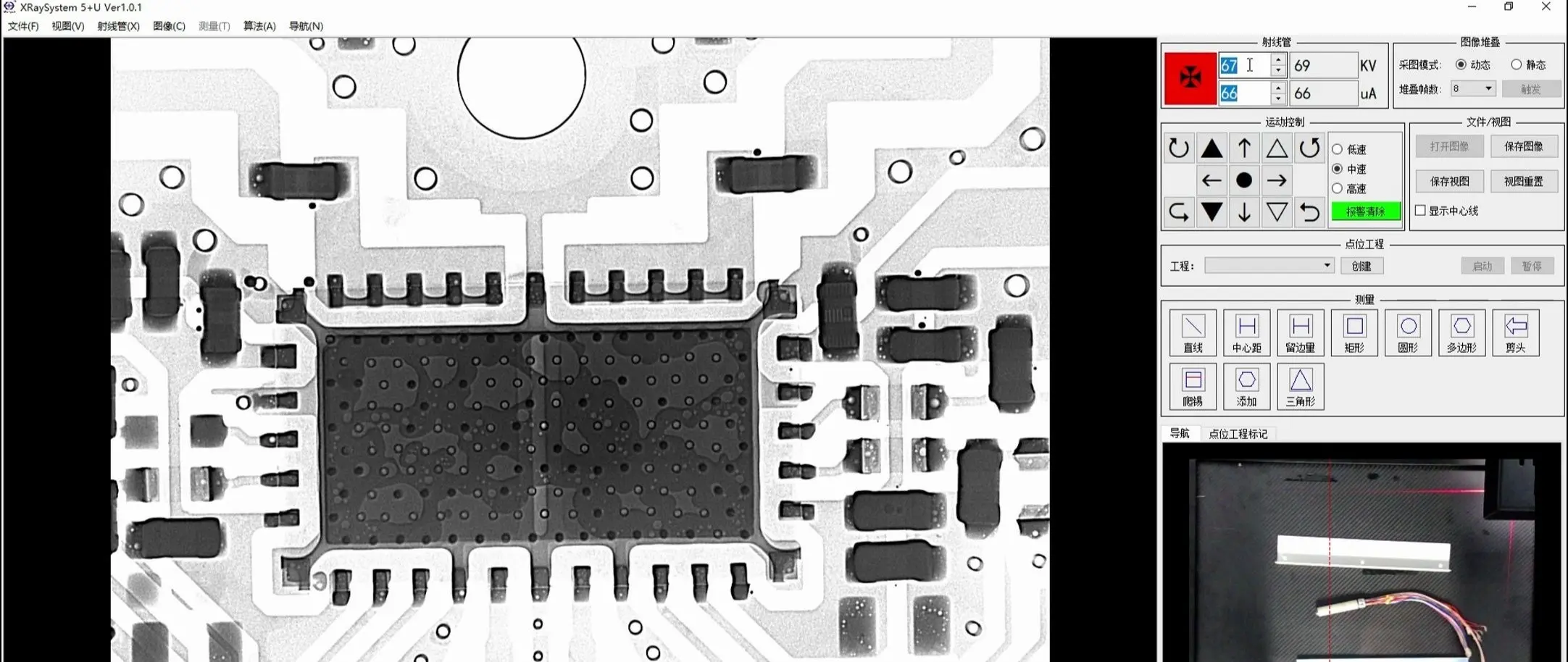
3. X-ray & Destructive Analysis
-
X-ray Inspection:
-
Diode Internal: Cathode metal area > anode (ratio 1.5:1);
-
Cap Internal: Anode foil etching grooves 30% deeper in electrolytic caps.
-
Precision: 2D X-ray res. ≤5μm; 3D CT slice thickness ≤1μm.
-
-
Destructive Verification:
-
Post-rework observation:
-
Diode chip cathode "P" mark;
-
Darker oxide layer on capacitor anode foil.
-
-
4. Error-Proof Design Optimization
-
Footprint Library:
-
Extend polarity markings by 0.3mm (prevent silkscreen misalignment coverage);
-
Unify diode cathode band orientation to +X axis (IPC-7351B).
-
-
Reflow Process:
-
Asymmetric Pads (anode pad area=1.2× cathode) leverage surface tension for self-alignment:
Anode Pad: 1.5×0.8mm Cathode Pad: 1.2×0.8mm
-
5. Failure Data & Improvement
| Stage | Error Detection Rate | Main Failure Mode | Corrective Action |
|---|---|---|---|
| AOI | 98.5% | Faded print/shadowing | Add RGB triple-light source |
| ICT | 99.2% | Poor test point contact | Dual-contact spring probes |
| X-ray | 100% | Internal defects | Monthly X-ray grayscale cal. |
Conclusion
Polarity error detection requires "optical + electrical + structural" triple-lock:
-
Tier 1: AOI strict marking comparison (band/"±" symbol), accuracy ≥99.5%;
-
Tier 2: Electrical static tests (abnormal leakage/ESR);
-
Final Tier: X-ray internal verification (anode/cathode feature ratios).
Design Redlines: -
Never use 180° symmetric pads for polarized parts;
-
Class 3 products require 100% X-ray sampling (AQL 0.65).