 PCB
PCB FPC
FPC Rigid-Flex
 FR-4
FR-4 HDI PCB
 Rogers High-Frequency Board
 PTFE Teflon High-Frequency Board
 Aluminum
 Copper Core
 PCB Assembly
 LED light PCBA
 Memory PCBA
 Power Supply PCBA
 New Energey PCBA
 Communication PCBA
 Industrial Control PCBA
 Medical Equipment PCBA
 Testing Service
 PCBA Testing Service
 Certification Application
 RoHS Certification Application
 REACH Certification Application
 CE Certification Application
 FCC Certification Application
 CQC Certification Application
 UL Certification Application
 Transformers, Inductors
 High Frequency Transformers
 Low Frequency Transformers
 High Power Transformers
 Conversion Transformers
 Sealed Transformers
 Ring Transformers
 Inductors
 Wires,Cables Customized
 Network Cables
 Power Cords
 Antenna Cables
 Coaxial Cables
 Net Position Indicator
 Solar AIS net position indicator
 Capacitors
 Connectors
 Diodes
 Embedded Processors & Controllers
 Digital Signal Processors (DSP/DSC)
 Microcontrollers (MCU/MPU/SOC)
 Programmable Logic Device(CPLD/FPGA)
 Communication Modules/IoT
 Resistors
 Through Hole Resistors
 Resistor Networks, Arrays
 Potentiometers,Variable Resistors
 Aluminum Case,Porcelain Tube Resistance
 Current Sense Resistors,Shunt Resistors
 Switches
 Transistors
 Power Modules
 Isolated Power Modules
 AC-DC Power Modules
 DC-AC Module(Inverter)
 RF and Wireless
Detailed Explanation of JFET
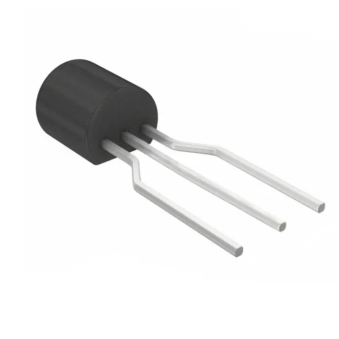
Detailed Explanation of JFET
JFET, short for Junction Field-Effect Transistor, is a special type of semiconductor transistor. The following is a detailed explanation of JFET:
I. Basic Structure and Types
1、Basic Structure: A JFET consists of a source (S), a drain (D), and a gate (G) control electrode. The source and drain form a junction field controlled by the gate, thereby regulating the direction of electron flow.
2、Types:
N-channel JFET: Allows electrons to serve as the primary charge carriers.
P-channel JFET: Allows holes to flow.
II. Operating Principle
JFET is a voltage-controlled device that operates by altering the conductivity of the channel through changes in the gate voltage, thereby controlling the output current. Specifically:
1、Depletion Mode: JFET primarily operates in depletion mode. In this mode, changes in gate voltage alter the width of the PN junction barrier between the gate and the channel, subsequently changing the length and thickness of the channel, which in turn affects the channel resistance, causing the drain current (Ids) to vary accordingly.
2、Conductivity Control: The gate voltage controls the conductivity of the channel by altering the carrier concentration within it. For an N-channel JFET, a negative gate voltage attracts electrons in the channel, reducing the carrier concentration and decreasing conductivity; conversely, a positive gate voltage increases the carrier concentration and enhances conductivity. The opposite applies to P-channel JFETs.
III. Key Characteristics
1、High Input Impedance: The input of a JFET is a reverse-biased PN junction, resulting in extremely high input impedance, facilitating matching with signal sources.
2、Low Noise: As carriers in the channel are unaffected by the semiconductor surface, JFETs exhibit high mobility and low noise.
3、Low Power Consumption: JFETs provide low power consumption and consumption efficiency, enhancing the overall efficiency of circuits.
4、Simple Biasing: The biasing circuit of a JFET is relatively simple, requiring no complex external biasing sources.
IV. Applications
1、Signal Amplification: JFETs can be used as preamplifiers, offering high input impedance and a low-noise signal path.
2、Switching Applications: Due to their rapid switching characteristics, JFETs are often used as switches in digital circuits.
3、Constant Current Sources: Utilizing the characteristics of JFETs in the constant current region, stable constant current source circuits can be constructed.
V. Comparison with MOSFET
1、Gate Structure: JFETs use PN junctions as gates, while MOSFETs employ metal-oxide-semiconductor structures.
2、Operating Modes: JFETs only operate in depletion mode, whereas MOSFETs have both depletion and enhancement modes.
3、Conduction Mechanism: Although JFETs and MOSFETs differ in conduction mechanisms, they both function as voltage-controlled devices.