PCB
PCB FPC
FPC Rigid-Flex
 FR-4
FR-4 HDI PCB
 Rogers High-Frequency Board
 PTFE Teflon High-Frequency Board
 Aluminum
 Copper Core
 PCB Assembly
 LED light PCBA
 Memory PCBA
 Power Supply PCBA
 New Energey PCBA
 Communication PCBA
 Industrial Control PCBA
 Medical Equipment PCBA
 Testing Service
 PCBA Testing Service
 Certification Application
 RoHS Certification Application
 REACH Certification Application
 CE Certification Application
 FCC Certification Application
 CQC Certification Application
 UL Certification Application
 Transformers, Inductors
 High Frequency Transformers
 Low Frequency Transformers
 High Power Transformers
 Conversion Transformers
 Sealed Transformers
 Ring Transformers
 Inductors
 Wires,Cables Customized
 Network Cables
 Power Cords
 Antenna Cables
 Coaxial Cables
 Net Position Indicator
 Solar AIS net position indicator
 Capacitors
 Connectors
 Diodes
 Embedded Processors & Controllers
 Digital Signal Processors (DSP/DSC)
 Microcontrollers (MCU/MPU/SOC)
 Programmable Logic Device(CPLD/FPGA)
 Communication Modules/IoT
 Resistors
 Through Hole Resistors
 Resistor Networks, Arrays
 Potentiometers,Variable Resistors
 Aluminum Case,Porcelain Tube Resistance
 Current Sense Resistors,Shunt Resistors
 Switches
 Transistors
 Power Modules
 Isolated Power Modules
 AC-DC Power Modules
 DC-AC Module(Inverter)
 RF and Wireless
CTE-Matched Substrate & Plating Selection for High-Temp PCBs
In high-temperature environments (>150℃), CTE mismatch causes plating cracks and solder joint failures. A Z-axis CTE difference >5ppm/℃ leads to 90% solder crack risk after 200 thermal cycles (-55℃~175℃). This guide details selection strategies through material analysis, matching models, and validation data.
1. CTE Mismatch Mechanisms
1.1 Thermal Stress Model
Interlayer stress (σ):
Where:
-
: ElastIC modulus (GPa)
-
: Poisson's ratio
-
: CTE difference (ppm/℃)
-
: Temperature swing (℃)
Critical Threshold: Microcracks form when > 120MPa
1.2 Failure Modes
| Failure Type | CTE Mismatch | Symptom | Microscopic Feature |
|---|---|---|---|
| Plating Crack | >8ppm/℃ | PTH Barrel Fracture | 45° Oblique Cracks (SEM) |
| Solder Joint Failure | >6ppm/℃ | BGA Ball Lift-off | IMC Layer Fracture |
| Delamination | >10ppm/℃ | Z-Axis Blistering | >5% Delam Area (C-SAM) |
2. Substrate Selection
2.1 High-Temp Material CTE
| Material | XY-CTE (ppm/℃) | Z-CTE (ppm/℃) | Tg (℃) | Temp Limit |
|---|---|---|---|---|
| FR-4 (Standard) | 14-16 | 50-70 | 130-140 | <130℃ |
| High-Tg Epoxy | 12-14 | 40-45 | 170-180 | 150℃ |
| Polyimide (PI) | 12-15 | 35-40 | >250 | 200℃ |
| Ceramic-Filled PTFE | 10-12 | 25-30 | >300 | 250℃ |
| Metal Core (Al) | 23 (Al) | 12 (Insul.) | N/A | Thermal Priority |
2.2 Substrate-Plating CTE Matrix
| Plating Type | CTE (ppm/℃) | Recommended Substrate | Risk Level |
|---|---|---|---|
| ENIG | 13-15 | PI/PTFE | ★☆☆ (Low) |
| Immersion Ag | 19-22 | High-Tg Epoxy | ★★☆ (Med) |
| Immersion Sn | 23-26 | Metal Core | ★★★ (High) |
| Electroplated Hard Au | 14.2 | Ceramic PTFE | ★☆☆ (Low) |
3. Plating Optimization
3.1 Composite Plating Structure (Fig.2)
PTH Hole Solution:
-
Electroless Ni: CTE 13.5ppm/℃ (8wt% P)
-
Transition Layer: Nanocrystalline Ni (CTE 10.5ppm/℃)
-
SuRFace Layer: Hard Au (CTE 14.2ppm/℃)
Result: Z-axis CTE gradient <3ppm/℃
3.2 Key Process Parameters
| Process | Parameter | CTE Impact Mechanism |
|---|---|---|
| Electroless Ni | P Content 8±0.5wt% | ∓0.8ppm/℃ per ±1% P |
| Electroplated Cu | Current Density 1.5ASD | Columnar Grain CTE +15% |
| Annealing | 150℃×2h (N₂) | Stress Relief, CTE -8% |
4. Validation & Case Study
4.1 Thermal Cycling Data (-55℃↔175℃)
| Material Stack | Failure Rate @500cyc | Failure Location |
|---|---|---|
| FR-4 + Immersion Sn | 100% | BGA Joint Interface |
| PI Substrate + ENIG | 12% | PTH Microcracks |
| Ceramic PTFE + Composite | 0% | No Failure |
4.2 Mars Rover PSU Module
-
Environment: -120℃~+125℃ (Diurnal Cycle)
-
Materials:
-
Substrate: Ceramic-Filled PTFE (Z-CTE=28ppm/℃)
-
Plating: Ni/Hard Au Composite (CTE=12.8ppm/℃)
-
-
Results:
-
PTH Resistance Change <2% after 3000 cycles
-
Zero Microcracks (SEM, Fig.3)
-
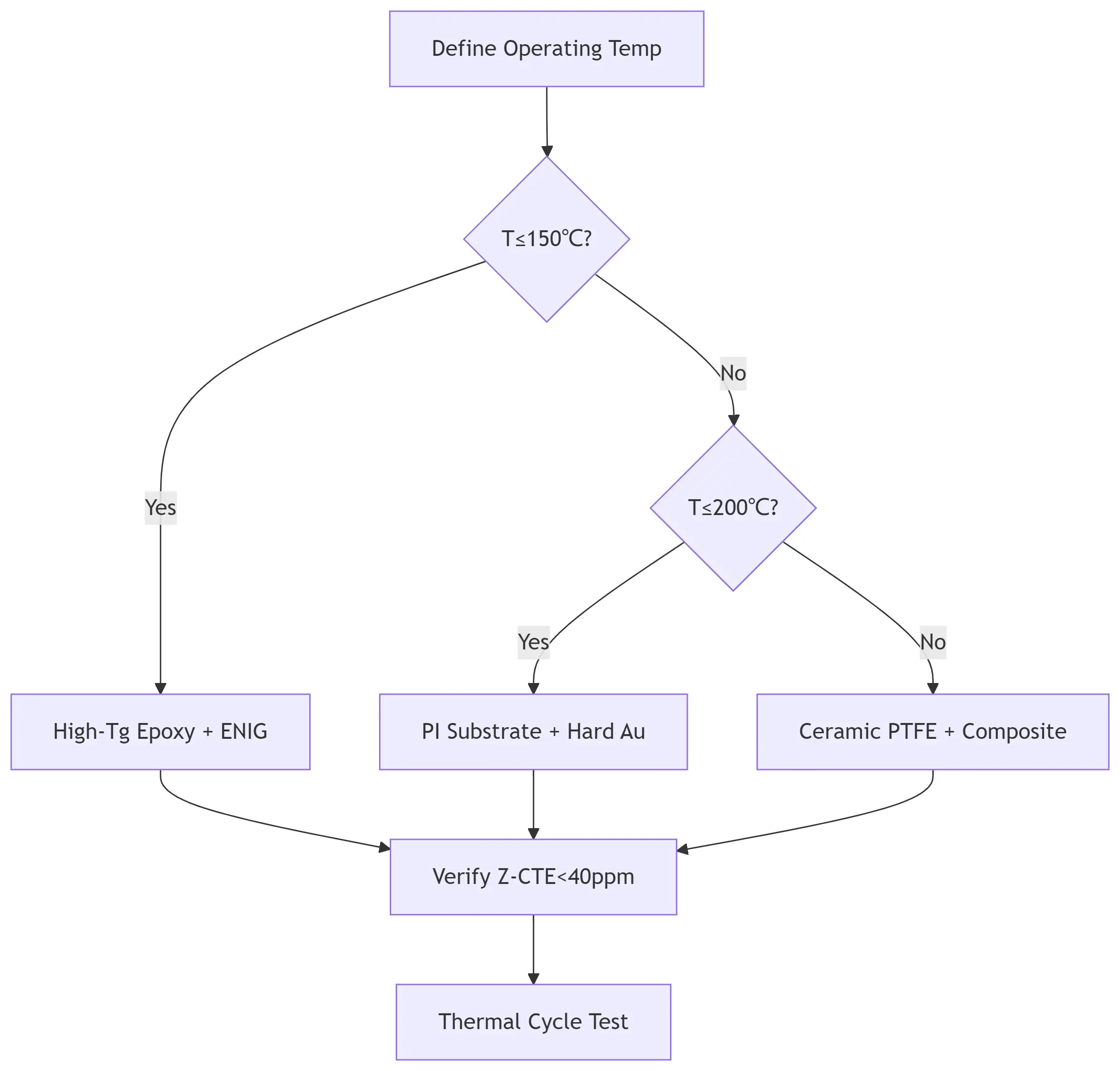
5. Selection Flowchart