 PCB
PCB FPC
FPC Rigid-Flex
 FR-4
FR-4 HDI PCB
 Rogers High-Frequency Board
 PTFE Teflon High-Frequency Board
 Aluminum
 Copper Core
 PCB Assembly
 LED light PCBA
 Memory PCBA
 Power Supply PCBA
 New Energey PCBA
 Communication PCBA
 Industrial Control PCBA
 Medical Equipment PCBA
 Testing Service
 PCBA Testing Service
 Certification Application
 RoHS Certification Application
 REACH Certification Application
 CE Certification Application
 FCC Certification Application
 CQC Certification Application
 UL Certification Application
 Transformers, Inductors
 High Frequency Transformers
 Low Frequency Transformers
 High Power Transformers
 Conversion Transformers
 Sealed Transformers
 Ring Transformers
 Inductors
 Wires,Cables Customized
 Network Cables
 Power Cords
 Antenna Cables
 Coaxial Cables
 Net Position Indicator
 Solar AIS net position indicator
 Capacitors
 Connectors
 Diodes
 Embedded Processors & Controllers
 Digital Signal Processors (DSP/DSC)
 Microcontrollers (MCU/MPU/SOC)
 Programmable Logic Device(CPLD/FPGA)
 Communication Modules/IoT
 Resistors
 Through Hole Resistors
 Resistor Networks, Arrays
 Potentiometers,Variable Resistors
 Aluminum Case,Porcelain Tube Resistance
 Current Sense Resistors,Shunt Resistors
 Switches
 Transistors
 Power Modules
 Isolated Power Modules
 AC-DC Power Modules
 DC-AC Module(Inverter)
 RF and Wireless
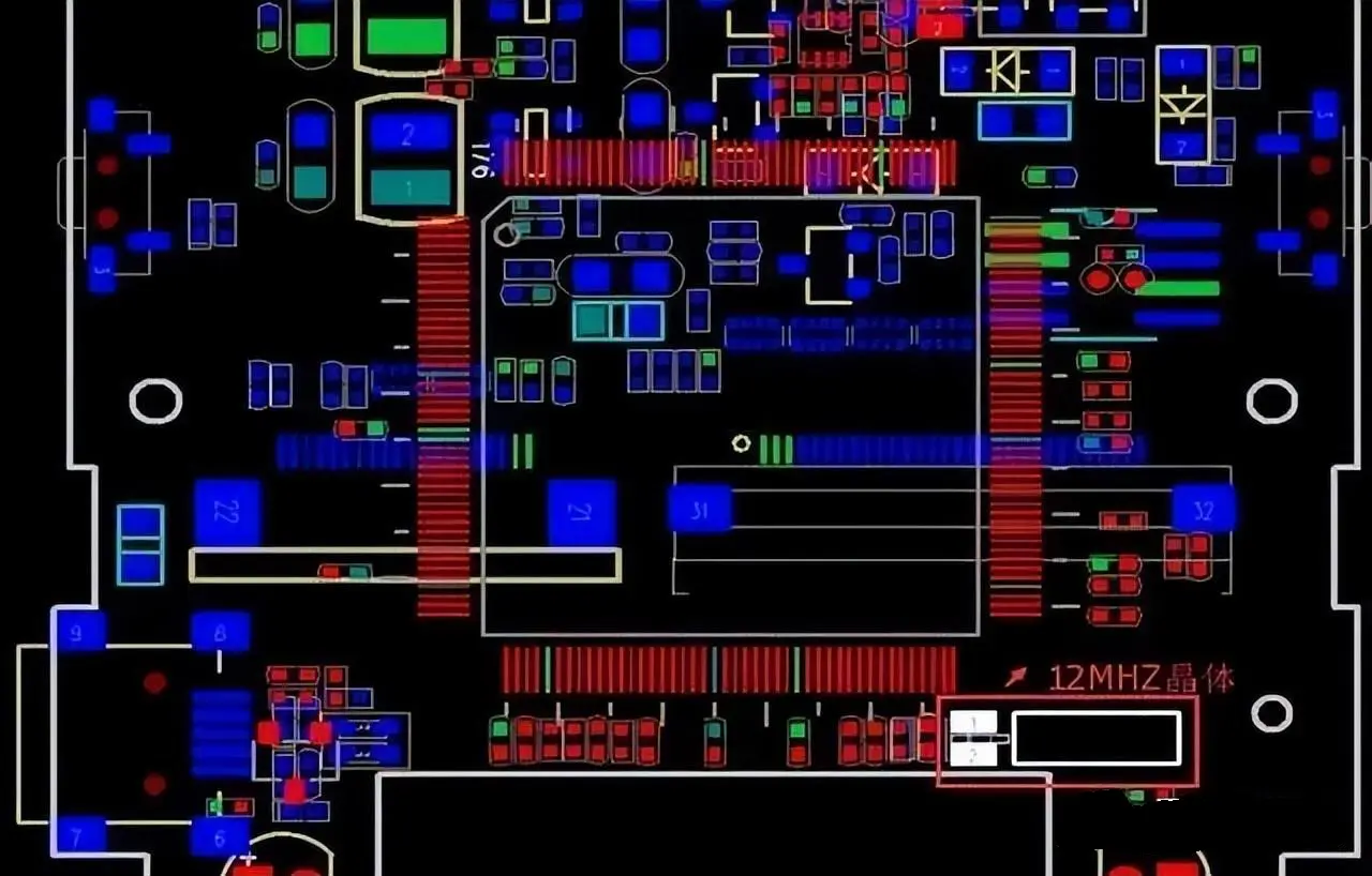
Why Can't a Crystal Oscillator Be Placed on the Edge of a PCB?
Why Can't a Crystal Oscillator Be Placed on the Edge of a PCB?
The reasons why a crystal oscillator should not be placed on the edge of a PCB mainly involve electromagnetic inteRFerence, heat dissipation conditions, mechanical stress, and wiring design.

I. Electromagnetic Interference
Electromagnetic Field Strength: The edges of a PCB are the primary areas for current and signal transmission, thus the electromagnetic field intensity here is relatively high. If a crystal oscillator is placed on the edge, it will be subjected to strong electromagnetic interference, resulting in decreased frequency stability.
Electromagnetic Interference Formula: EMI = k * f * n * v * d / r². Where EMI represents the electromagnetic interference intensity, k is a constant, f is the frequency, n is the current intensity, v is the voltage, d is the distance, and r is the radius. This formula indicates that the electromagnetic interference intensity is related to frequency, current intensity, and distance. The closer the distance (e.g., the crystal oscillator being near the edge of the PCB), the stronger the electromagnetic interference.
II. Heat Dissipation Conditions
Thermal Stability Formula: ΔT = K * ΔQ * r² / (T * π² * k * d²). Where ΔT represents the temperature change, K is a constant, ΔQ is the heat change, r is the radius, T is the absolute temperature, k is the thermal conductivity, and d is the distance. This formula shows that the temperature change is related to the heat change, distance, and radius. The farther the distance, the smaller the temperature change. Therefore, placing a crystal oscillator on the edge of a PCB will expose it to larger temperature variations in its operating environment, affecting its performance.
Heat Dissipation Requirements: The position at the edge of a PCB is generally unfavorable for heat dissipation. If a crystal oscillator is placed on the edge, its operating environment may change due to temperature variations, leading to frequency drift.
III. Mechanical Stress
Mechanical Pressure: During the PCB assembly process, the edge positions may be subjected to greater mechanical pressure. These stresses may be transmitted to the crystal oscillator, causing its performance to degrade.
Force Area: When a crystal oscillator is placed on the edge, its force area may be smaller, increasing the stress per unit area and further affecting its performance.
IV. Wiring Design
Signal Interference: Signal lines cannot be laid under a crystal oscillator as it can easily cause the signal lines to couple harmonic noise from the crystal oscillator. If a crystal oscillator is placed on the edge, it may increase the difficulty of wiring, making the signal lines more susceptible to interference.
Wiring Rules: In Pcb Design, critical signal lines (such as clock signal lines) should be prioritized and kept as short and direct as possible. As a clock signal source, the position of a crystal oscillator has a significant impact on wiring design. Placing a crystal oscillator on the edge may not facilitate the optimal arrangement of clock signal lines.
To avoid electromagnetic interference, heat dissipation issues, mechanical stress, and wiring design difficulties, it is generally not recommended to place a crystal oscillator on the edge of a PCB. During PCB layout, these factors should be comprehensively considered to place the crystal oscillator in a suitable position to ensure the stability and reliability of the circuit.