 PCB
PCB FPC
FPC Rigid-Flex
 FR-4
FR-4 HDI PCB
 Rogers High-Frequency Board
 PTFE Teflon High-Frequency Board
 Aluminum
 Copper Core
 PCB Assembly
 LED light PCBA
 Memory PCBA
 Power Supply PCBA
 New Energey PCBA
 Communication PCBA
 Industrial Control PCBA
 Medical Equipment PCBA
 Testing Service
 PCBA Testing Service
 Certification Application
 RoHS Certification Application
 REACH Certification Application
 CE Certification Application
 FCC Certification Application
 CQC Certification Application
 UL Certification Application
 Transformers, Inductors
 High Frequency Transformers
 Low Frequency Transformers
 High Power Transformers
 Conversion Transformers
 Sealed Transformers
 Ring Transformers
 Inductors
 Wires,Cables Customized
 Network Cables
 Power Cords
 Antenna Cables
 Coaxial Cables
 Net Position Indicator
 Solar AIS net position indicator
 Capacitors
 Connectors
 Diodes
 Embedded Processors & Controllers
 Digital Signal Processors (DSP/DSC)
 Microcontrollers (MCU/MPU/SOC)
 Programmable Logic Device(CPLD/FPGA)
 Communication Modules/IoT
 Resistors
 Through Hole Resistors
 Resistor Networks, Arrays
 Potentiometers,Variable Resistors
 Aluminum Case,Porcelain Tube Resistance
 Current Sense Resistors,Shunt Resistors
 Switches
 Transistors
 Power Modules
 Isolated Power Modules
 AC-DC Power Modules
 DC-AC Module(Inverter)
 RF and Wireless
Controlling Cutting Dimensional Accuracy of Ordinary FR-4 Substrates
2025-09-20
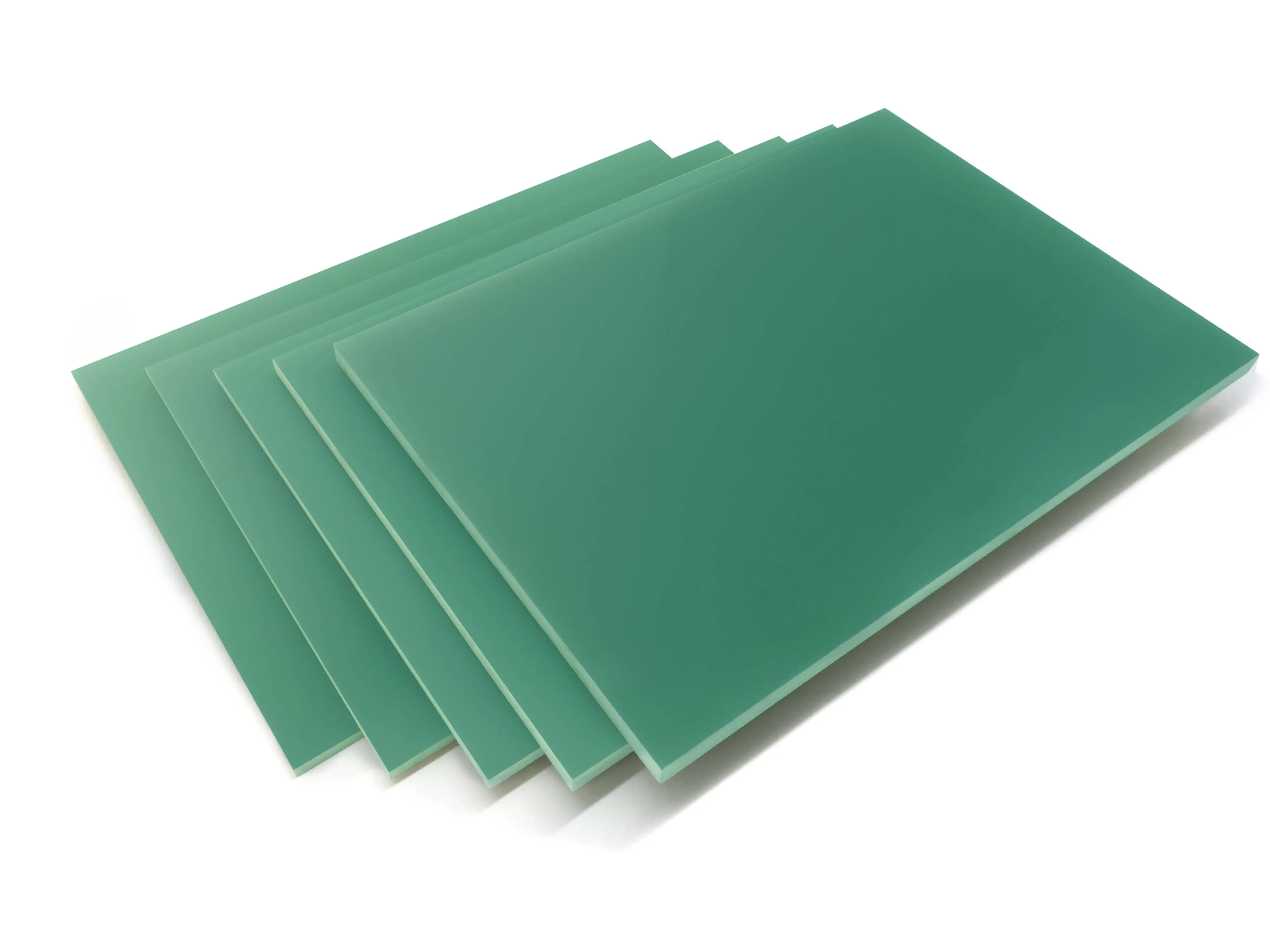
Importance of FR-4 Substrate Cutting Accuracy
Ordinary FR-4 substrate is the most widely used rigid printed Circuit Board base material in the electronics industry. Its cutting process is a key pre-process in PCB manufacturing, aiming to cut large-sized copper-clad plates (such as 1220mm×1020mm) into small-sized substrates (such as 500mm×400mm) that meet the requirements of subsequent processing (such as drilling and etching). Cutting dimensional accuracy directly affects the processing quality of subsequent processes — excessive dimensional deviation may lead todrilling deviation, misalignment between circuit patterns and pads, component installation inteRFerence and other problems, and may even cause the scrapping of the entire batch of substrates in severe cases.
Industry standards for the cutting dimensional accuracy of ordinary FR-4 substrates usually require: length/width tolerance ±0.1mm~±0.2mm (adjusted according to substrate thickness, smaller value for thin substrates), diagonal deviation ≤0.3mm/m, and edge perpendicularity ≤0.1mm/m. Therefore, systematic process control measures are needed to ensure that the cutting accuracy of FR-4 substrates stably meets the standards.
1. Influencing Factors of FR-4 Substrate Cutting Dimensional Accuracy
The cutting accuracy of FR-4 substrates is comprehensively affected by various factors, which need to be identified and controlled in a targeted manner:
- Substrate Characteristics: FR-4 substrate is composed of glass fiber cloth and epoxy resin, with certain elasticity and brittleness, which is prone to "burrs" and "delamination" during cutting; thickness deviation (usually ±0.05mm) will also lead to uneven cutting pressure, affecting dimensional accuracy.
- Cutting Equipment Accuracy: The straightness of the equipment's guide rail, the parallelism of the knife shaft, and the accuracy of the positioning system directly determine the cutting benchmark. Old equipment is prone to accuracy degradation due to component wear.
- Cutting Process Parameters: Improper setting of cutting speed, pressure, and tool angle will cause substrate stretching deformation or excessive tool wear, leading to dimensional deviation.
- Positioning and Fixing Methods: Inaccurate substrate positioning or insecure fixing will easily cause displacement during cutting, resulting in dimensional deviation.
2. Methods for Controlling Cutting Dimensional Accuracy
2.1 Control of Preparation Work Before Cutting
Preparation work before cutting is the basis for ensuring accuracy, and focus should be paid to substrate pretreatment and equipment calibration:
- Substrate Pretreatment and Inspection: Check the original size and flatness of the FR-4 substrate, and select substrates with thickness deviation ≤±0.03mm and flatness ≤0.2mm/m to avoid dimensional fluctuations after cutting due to inherent defects of the substrate.
- Carry out "aging treatment" on the substrate — place it in an environment of 23±2℃ and 50±5%RH for 24 hours to release internal stress of the substrate and reduce dimensional shrinkage caused by stress release after cutting (usually shrinkage rate ≤0.05%).
Equipment Calibration and Inspection: Before cutting every day, calibrate the straightness of the equipment guide rail (requirement ≤0.01mm/m) and the parallelism of the knife shaft (requirement ≤0.02mm) with a laser interferometer; calibrate the coordinate accuracy of the positioning platform with a standard gauge block (accuracy ±0.001mm) to ensure that the X/Y axis positioning error ≤±0.005mm.
Check the edge state of the cutting tool (such as diamond circular knife, cemented carbide knife). When the edge wear amount >0.02mm or chipping occurs, it should be replaced in time to avoid excessive burrs or dimensional deviation caused by tool wear.
2.2 Selection of Cutting Equipment and Optimization of Process Parameters
Select appropriate cutting equipment and optimize process parameters according to the thickness and size requirements of FR-4 substrates:
- Equipment Selection: For thin substrates with thickness ≤1.6mm, CNC laser cutting machine (wavelength 1064nm) is recommended, with cutting accuracy up to ±0.05mm, no burrs on the edge, and no deformation caused by mechanical stress;
- For thick substrates with thickness 1.6mm~6.0mm, select high-precision CNC plate cutting machine (equipped with servo motor and ball screw drive), with positioning accuracy ≤±0.01mm and repeated positioning accuracy ≤±0.005mm.
Process Parameter Optimization: Cutting Speed: The cutting speed of thin substrates (≤1.6mm) is controlled at 100~150mm/s, and that of thick substrates (>1.6mm) is reduced to 50~100mm/s. Excessive speed is easy to cause substrate vibration and affect dimensional accuracy.
Cutting Pressure: Adjust according to substrate thickness. The pressure should ensure that the substrate is tightly fixed without deformation. Usually, the pressure for thin substrates is 5~8kg/cm², and that for thick substrates is 8~12kg/cm². It can be monitored and adjusted in real time by a pressure sensor.
Tool Angle: The cutting angle of cemented carbide tools is recommended to be 30°~45°, and the relief angle is 10°~15° to ensure that the cutting edge is sharp and not easy to chip; the power of laser cutting should match the substrate thickness, and the power for 1.6mm thick substrates is usually 30~40W, with frequency 50~100kHz.
2.3 Control of Positioning and Fixing Methods
Accurate positioning and firm fixing are the keys to preventing cutting displacement:
- Positioning Method: Adopt "reference edge + positioning pin" dual positioning: first use a right-angle edge of the substrate as the reference edge, and lean it against the reference stop of the equipment (perpendicularity ≤0.01mm/m); then insert 2~4 positioning pins (diameter tolerance ±0.005mm) into the pre-positioning holes of the substrate to ensure that the substrate has no rotation or translation during cutting.
- For substrates without pre-positioning holes, use a CCD visual positioning system (accuracy ±0.003mm) to position by identifying the substrate edge or marking points. The positioning time is ≤2 seconds per piece, which is suitable for mass production.
Fixing Method: Adopt "vacuum adsorption + pressing strip" composite fixing: vacuum adsorption holes are evenly distributed (spacing 50~80mm), and the adsorption force ≥0.06MPa to ensure that the substrate is closely attached to the positioning platform; at the same time, set metal pressing strips (width 10~15mm) on the edge of the substrate, and the pressing strip pressure is 3~5kg/cm² to further prevent substrate warping during cutting.
2.4 Quality Inspection and Feedback Adjustment After Cutting
Continuously optimize cutting accuracy through strict inspection and feedback mechanisms:
- Dimensional Inspection: First article inspection: For the first 3 substrates in each batch, measure the length, width, and diagonal dimensions with a high-precision vernier caliper (accuracy ±0.01mm) or an image measuring instrument (accuracy ±0.001mm), record the deviation value. If it exceeds the tolerance range (such as ±0.1mm), re-calibrate the equipment parameters.
- Batch sampling inspection: Sample 1 substrate for inspection every 50 substrates produced, with the same inspection items as the first article. If deviation trends occur in 3 consecutive pieces (such as gradually increasing size), stop the machine to check tool wear or equipment positioning accuracy.
Edge Quality Inspection: Check the burr height of the cutting edge with a microscope (magnification 20~50 times), requiring ≤0.03mm, no delamination or cracking; if the burr exceeds the standard, replace the tool or reduce the cutting speed.
Feedback Adjustment: Establish a dimensional deviation ledger, record the deviation data of each batch, find out the deviation law through statistical analysis (such as the size in a certain direction is always small), and adjust the equipment positioning parameters in a targeted manner (such as X-axis compensation +0.02mm).
3. Common Problems and Solutions
| Common Problems | Causes | Solutions |
|---|---|---|
| Cutting size is too large/small | Equipment positioning parameter deviation; insufficient cutting amount due to tool wear; substrate shrinkage rate not compensated | Re-calibrate equipment positioning coordinates; replace with new tools; set compensation value in the cutting program according to substrate shrinkage rate (measured value) (such as +0.03mm) |
| Diagonal deviation exceeds standard | Equipment X/Y axis perpendicularity deviation; substrate positioning reference edge is not perpendicular | Calibrate X/Y axis perpendicularity with laser interferometer (requirement ≤0.01mm/m); replace the reference edge and select the substrate edge with qualified perpendicularity as the positioning reference |
| Excessive edge burrs | Tool edge wear; excessive cutting speed; insufficient pressure leading to substrate vibration | Replace tools; reduce cutting speed to below 80mm/s; increase vacuum adsorption force to 0.08MPa |
| Substrate warping after cutting | Uneven fixing pressure; substrate internal stress not released; cutting direction inconsistent with glass fiber cloth texture | Adjust the pressure of the pressing strip to ensure uniform force; extend the substrate aging treatment time to 48 hours; cut along the texture direction of the glass fiber cloth (texture direction should be marked in advance) |