 PCB
PCB FPC
FPC Rigid-Flex
 FR-4
FR-4 HDI PCB
 Rogers High-Frequency Board
 PTFE Teflon High-Frequency Board
 Aluminum
 Copper Core
 PCB Assembly
 LED light PCBA
 Memory PCBA
 Power Supply PCBA
 New Energey PCBA
 Communication PCBA
 Industrial Control PCBA
 Medical Equipment PCBA
 Testing Service
 PCBA Testing Service
 Certification Application
 RoHS Certification Application
 REACH Certification Application
 CE Certification Application
 FCC Certification Application
 CQC Certification Application
 UL Certification Application
 Transformers, Inductors
 High Frequency Transformers
 Low Frequency Transformers
 High Power Transformers
 Conversion Transformers
 Sealed Transformers
 Ring Transformers
 Inductors
 Wires,Cables Customized
 Network Cables
 Power Cords
 Antenna Cables
 Coaxial Cables
 Net Position Indicator
 Solar AIS net position indicator
 Capacitors
 Connectors
 Diodes
 Embedded Processors & Controllers
 Digital Signal Processors (DSP/DSC)
 Microcontrollers (MCU/MPU/SOC)
 Programmable Logic Device(CPLD/FPGA)
 Communication Modules/IoT
 Resistors
 Through Hole Resistors
 Resistor Networks, Arrays
 Potentiometers,Variable Resistors
 Aluminum Case,Porcelain Tube Resistance
 Current Sense Resistors,Shunt Resistors
 Switches
 Transistors
 Power Modules
 Isolated Power Modules
 AC-DC Power Modules
 DC-AC Module(Inverter)
 RF and Wireless
Control of Stress Deformation in Lamination Process for Ultra-Thin Core (<0.1mm)
1. Core Challenges
Ultra-thin cores (<0.1mm) face critICal issues during lamination:
-
Thermal stress: CTE mismatch caused by temperature gradients;
-
Mechanical stress: Non-uniform pressure distribution;
-
Residual stress: Resin shrinkage and elastic recovery;
-
Interlayer slippage: Friction mismatch at core/copper-Prepreg inteRFaces.
2. Temperature Control
-
Multi-zone dynamic heating:
Independent temperature control (±1°C) across lamination zones. For copper-core-Prepreg stacks, set core temperature 5°C higher than copper to compensate CTE. -
Ramped thermal profiles:
Heating/cooling rates ≤3°C/min and ≤2°C/min, respectively. Peak temperature ≤Tg+20°C for low-Tg materials (e.g., FR-4).
3. Pressure Optimization
-
Progressive pressure loading:
0.5 MPa (5 min) →1.5 MPa (10 min) →2.5 MPa (5 min). -
Pressure equalization:
Silicone pads (30–50 Shore A) or graphite plates to limit pressure variation to ±5%.
4. Material Engineering
-
CTE matching:
Core/copper CTE difference <5 ppm/°C (e.g., Panasonic Prepreg CTE=12 ppm/°C with rolled copper). -
Surface activation:
O₂/N₂ plasma treatment (300 W, 60 s) rAISes surface energy to 50 mN/m for better adhesion.
5. Vacuum Lamination Process
-
Vacuum control:
Primary vacuum (10–100 mbar) for macro-void removal; high vacuum (<1 mbar) held for 20–30 min. -
Resin flow management:
Low-viscosity epoxy (<1000 cP @100°C) with flow channels to prevent resin pooling.
6. Residual Stress Mitigation
-
Symmetric stack design:
Balance copper thickness (<10% asymmetry) or add PI balancing layers. -
Post-curing:
Gradual cooling (1°C/min) under 0.5 MPa to release elastic strain.
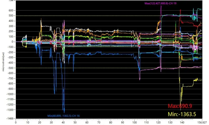
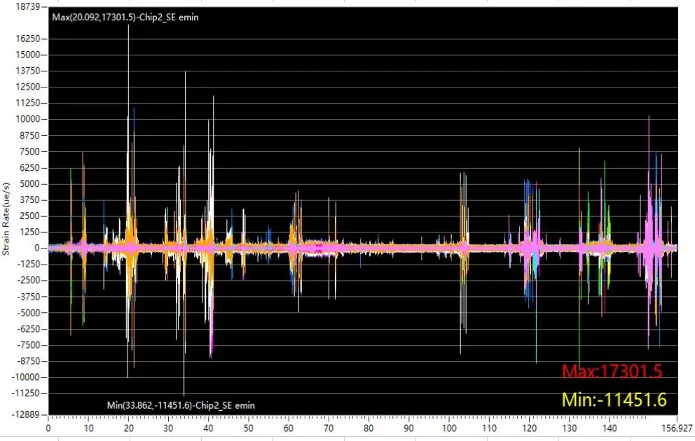
7. Real-Time Monitoring
-
FBG sensors:
Embedded fiber Bragg gratings monitor strain (1 με resolution). -
Thermal imaging:
Detect hotspots (>5°C variation) for dynamic adjustment. -
Laser profilometry:
Post-lamination warpage <0.1 mm/m.
8. Case Studies
-
Case 1: 50μm FR-4 core
-
Profile: 80°C→140°C→50°C (150 min total)
-
Results: Warpage reduced from 0.5 to 0.07 mm/m; peel strength >1.0 N/mm.
-
-
Case 2: 75μm PTFE high-frequency core
-
Ar plasma activation →220°C lamination @1.8 MPa
-
Results: Dk variation <0.02; hole positional accuracy ±25 μm.
-
9. Innovation Directions
-
Nano-cellulose reinforcement: Elastic modulus >8 GPa to prevent wrinkling.
-
Laser surface texturing: Ra=1–2 μm for mechanical interlocking on Rogers RO3000 cores.
-
AI-driven digital twins: Predictive compensation for process variations.