 PCB
PCB FPC
FPC Rigid-Flex
 FR-4
FR-4 HDI PCB
 Rogers High-Frequency Board
 PTFE Teflon High-Frequency Board
 Aluminum
 Copper Core
 PCB Assembly
 LED light PCBA
 Memory PCBA
 Power Supply PCBA
 New Energey PCBA
 Communication PCBA
 Industrial Control PCBA
 Medical Equipment PCBA
 Testing Service
 PCBA Testing Service
 Certification Application
 RoHS Certification Application
 REACH Certification Application
 CE Certification Application
 FCC Certification Application
 CQC Certification Application
 UL Certification Application
 Transformers, Inductors
 High Frequency Transformers
 Low Frequency Transformers
 High Power Transformers
 Conversion Transformers
 Sealed Transformers
 Ring Transformers
 Inductors
 Wires,Cables Customized
 Network Cables
 Power Cords
 Antenna Cables
 Coaxial Cables
 Net Position Indicator
 Solar AIS net position indicator
 Capacitors
 Connectors
 Diodes
 Embedded Processors & Controllers
 Digital Signal Processors (DSP/DSC)
 Microcontrollers (MCU/MPU/SOC)
 Programmable Logic Device(CPLD/FPGA)
 Communication Modules/IoT
 Resistors
 Through Hole Resistors
 Resistor Networks, Arrays
 Potentiometers,Variable Resistors
 Aluminum Case,Porcelain Tube Resistance
 Current Sense Resistors,Shunt Resistors
 Switches
 Transistors
 Power Modules
 Isolated Power Modules
 AC-DC Power Modules
 DC-AC Module(Inverter)
 RF and Wireless
Preventing Component Shifting in Lamination of Embedded Passive Devices
Embedded passive components (EPCs, e.g., Resistors/capacitors) enable high-density PCB integration but face post-lamination shifting (>50μm) due to thermal-mechanical stresses, causing impedance mismatch and signal loss. This guide details anti-shifting strategies through material matching, structural design, and process optimization to achieve ±15μm placement accuracy.
1. Shifting Mechanisms and Key Factors
1.1 Thermo-Mechanical Model (Figure 1)
Shifting distance (Δ) during lamination:
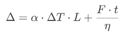
where:
-
α: CTE mismatch (target <2ppm/℃)
-
F: Resin flow shear force (dependent on viscosity η)
-
L: Component size, t: Pressure duration
1.2 Shifting Modes
-
Lateral slippage: XY-plane movement from resin flow imbalance;
-
Vertical lift: Z-axis deformation due to adhesive shrinkage;
-
Angular rotation: Common in components with aspect ratio >3.
2. Material System Optimization
2.1 CTE Matching
| Material | CTE (ppm/℃) | Application |
|---|---|---|
| FR-4 | 14-16 | General EPCs |
| Modified Epoxy | 8-10 | High-Frequency EPCs |
| LCP | 3-5 | Ultra-Thin Flex EPCs |
2.2 Adhesive Selection
-
Flowability: 500-1000cPs@150℃ (shear-thinning);
-
Cure shrinkage: <0.3% (per IPC-TM-650 2.4.41);
-
Tg: 10℃ above lamination peak temperature.
3. Anti-Shifting Structures
3.1 Mechanical Alignment (Figure 2)
-
Alignment slots:
-
Depth = 0.8×component thickness, clearance ≤10μm;
-
Chamfer radius R=0.05mm for easy insertion;
-
-
Micro-pillar arrays: φ0.2mm Cu pillars around components (0.5mm pitch) to block resin flow.
3.2 Stackup Compensation
-
Balanced layers: Add dummy components symmetrically;
-
Buffer rings: 0.1mm wide prepreg around EPCs to absorb stress.
4. Lamination Process Optimization
4.1 Temperature-Pressure Profile (Figure 3)
-
Staged heating:
-
Phase 1: 80℃→100℃@2℃/min, 0.5MPa pre-cure;
-
Phase 2: 100℃→180℃@1℃/min, 2.0MPa pressing;
-
-
Controlled cooling: 1℃/min cooling to 60℃ under pressure.
4.2 Vacuum Assistance
-
Multi-stage vacuum:
-
Initial: -90kPa for macro-void removal;
-
Pressing: -50kPa for stable resin flow;
-
-
Vacuum delay: 10min pre-pressurization to reduce porosity.
5. Inspection and Correction
5.1 In-line Monitoring
-
X-ray imaging: 5μm resolution for real-time feedback;
-
FBG sensors: Embedded strain monitoring (±2με accuracy).
5.2 Shifting Compensation
-
Laser adjustment: Local heating (10W, 50μm spot) for thermal realignment;
-
Conductive adhesive repair: Nano-silver paste (20nm particles) fills gaps.
6. Case Studies and Data
6.1 5G mmWave Antenna Module
-
Component: 0402 embedded resistor (100Ω), 0.5×0.25mm;
-
Results:
Metric Conventional Optimized Avg. shift 42μm 12μm Impedance error 8% 1.5% 28GHz RL -18dB -25dB
6.2 Reliability Tests
-
Thermal cycling: -55℃~125℃, 1000 cycles, <3μm shift increment;
-
Humidity aging: 85℃/85%RH, 500h, no delamination.
Conclusion
Coordinated CTE design, alignment structures, and precision lamination processes effectively suppress EPC shifting, meeting stringent tolerances for high-frequency circuits.