 PCB
PCB FPC
FPC Rigid-Flex
 FR-4
FR-4 HDI PCB
 Rogers High-Frequency Board
 PTFE Teflon High-Frequency Board
 Aluminum
 Copper Core
 PCB Assembly
 LED light PCBA
 Memory PCBA
 Power Supply PCBA
 New Energey PCBA
 Communication PCBA
 Industrial Control PCBA
 Medical Equipment PCBA
 Testing Service
 PCBA Testing Service
 Certification Application
 RoHS Certification Application
 REACH Certification Application
 CE Certification Application
 FCC Certification Application
 CQC Certification Application
 UL Certification Application
 Transformers, Inductors
 High Frequency Transformers
 Low Frequency Transformers
 High Power Transformers
 Conversion Transformers
 Sealed Transformers
 Ring Transformers
 Inductors
 Wires,Cables Customized
 Network Cables
 Power Cords
 Antenna Cables
 Coaxial Cables
 Net Position Indicator
 Solar AIS net position indicator
 Capacitors
 Connectors
 Diodes
 Embedded Processors & Controllers
 Digital Signal Processors (DSP/DSC)
 Microcontrollers (MCU/MPU/SOC)
 Programmable Logic Device(CPLD/FPGA)
 Communication Modules/IoT
 Resistors
 Through Hole Resistors
 Resistor Networks, Arrays
 Potentiometers,Variable Resistors
 Aluminum Case,Porcelain Tube Resistance
 Current Sense Resistors,Shunt Resistors
 Switches
 Transistors
 Power Modules
 Isolated Power Modules
 AC-DC Power Modules
 DC-AC Module(Inverter)
 RF and Wireless
(2)Analysis of SMT Mounter Mounting Precision Parameters and How to Measure Them
(2) Analysis of SMT Mounter Mounting Precision Parameters and How to Measure Them
2. Resolution of the Mounter
There are two types of resolutions commonly referred to for a mounter. One is the optICal resolution of the identification and correction camera, and the other is the mechanical resolution of each motion system of the machine.
Resolution is the physical basis for ensuring a certain precision of the machine.
1.Resolution and Precision of the Mounter
The resolution of a mounter usually refers to the resolution of the mounter's positioning system, specifically the minimum limit of mechanical displacement, which includes the minimum distance of X - Y movement and the minimum rotation angle of the Z - axis. Its value depends on the resolution of the servo mechanism, the shaft drive mechanism, and its measurement and control system. In fact, each system of the mounter, such as the optical system, various control and measurement sensors, has its own resolution.
The high resolution of the mounter is the basis for ensuring its precision, just as an instrument with high resolution is the basis for ensuring measurement accuracy. However, resolution is not directly related to precision. High resolution of some parts or all parts of the mounter does not guarantee high precision of the mounter. High resolution is only a necessary condition for high precision, not a sufficient condition, nor a necessary and sufficient condition. Generally, the resolution does not appear in the precision index of the mounter. The resolution index is only used when making an in - depth comparison of the overall peRFormance of the mounter.
At present, the Z - axis movement and rotation of high - precision mounters have reached resolutions of 0.001mm and 0.0024° respectively, and the resolution of each pixel of the vision system's camera has reached 0.038mm. With the development of precision manufacturing technology, these indicators will be further improved, thus ensuring the development of the mounter towards higher precision.
2.Optical Resolution of the Identification and Correction Camera
The optical resolution of the identification and correction camera is an inherent characteristic of the camera. The resolution of the mounter camera mainly refers to the size of the feature that can be recognized by one pixel of the camera. For example, 2.3 MPP (Mil Per Pixel) means 2.3 thousandths of an inch (58 μm) per pixel. The size of the pixel determines the size of the smallest feature that the machine can recognize. For components with pins, such as SOIC, QFP, and SOT, etc., the pitch between each of its pins requires 4 pixels to recognize. If a 2.3 in/pixel camera is used, then the smallest pitch it can recognize is: 4×2.3 = 9.2 (in) = 234 (μm), that is, 0.234mm.
Another parameter of the mounter camera is the number of pixels, which will determine the size of a single field of view of the camera. Older cameras mostly used 640×480 pixels. If the camera's resolution is 2.3 MPP, then the size of a single field of view is 37.3mm×28.0mm. Now, the number of pixels of newer digital cameras can reach 1024×1024 pixels, and the size of a single field of view of a 2.3 MPP camera can reach 59.8mm×59.8mm.
3.Mechanical Resolution of the Machine
The mechanical resolution of the machine is an inherent characteristic of the machine. It is a parameter that measures the working precision of each motion axis of the mounter, the basis for achieving the machine's precision, the minimum equivalent of mechanical displacement, and the tolerance fit between mechanical parts. The mechanical factors that affect the machine's precision include the machining accuracy of the installation plane of the machine worktable, the resolution of the worktable drive motor and drive lead - SCRew, the resolution of the encoder, the accuracy of the slide rails for axial movement of each axis, and the torsional deformation of the lead - screw, etc. Since there are many factors affecting the machine's precision and their mechanical resolutions are different, the mechanical resolution of the machine generally does not appear in the technical specifications of the machine.
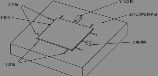
The installation plane of the machine worktable (as shown in the figure below) is generally made by milling a steel plate on the overall welded machine base frame plane through a machining center. The milling accuracy will determine the flatness of the platform. When milling, the machining center also drills positioning holes and threaded holes at predetermined positions to install and fix the slide rails, drive shafts, motors, and encoders of the worktable. The flatness of the platform and the accuracy of the positioning holes and threaded holes will affect the parallelism of the slide rails and the accuracy of the encoder. Now, the flatness and positioning accuracy of high - end equipment can reach above the micron level.
The resolution of the encoder is the main factor affecting the machine's precision. Common encoders include rotary encoders and linear encoders. Rotary encoders are generally installed behind the machine's moving axis or drive motor to feedback the moving distance of the tabletop through the rotation of the lead - screw, or directly feedback the rotation angle. The resolution of the rotary encoder is also called the resolution of the encoder. Now, the resolution of the rotary encoder can reach 36000 lines per revolution, that is, a resolution of 0.01 degree. The linear encoder, also known as the grating scale, can directly feedback the actual position of the worktable movement, without being affected by the torsional deformation of the transmission mechanism and the wear of the ball screw. The accuracy of the linear encoder of the mounter can reach 1μm or even higher.
The drive and control system of the worktable is also an important factor affecting the precision. For the two moving axes X and Y of the worktable, there are 3 common drive control methods, which are introduced separately below.
① The servo motor drives the lead - screw to drive the worktable X and Y to move, and the encoder coaxial with the motor or the lead - screw provides position feedback (as shown in the figure below). This control method belongs to semi - closed - loop control, and its accuracy mainly depends on the resolution of the encoder and the accuracy of the lead - screw. The advantage of this control method is that the control system and mechanical structure are relatively simple, the cost is low, and the stability is good. However, its drawback is that the encoder measures not the actual position of the worktable, but the rotation angle of the motor or the lead - screw, and then calculates the displacement value of the worktable. This method can only indirectly calculate the displacement of the worktable and cannot compensate for the mechanical errors and wear in the transmission link, such as the error of belt transmission, the torsional deformation of the lead - screw, and the pitch error, clearance, and wear between the lead - screw and the ball.
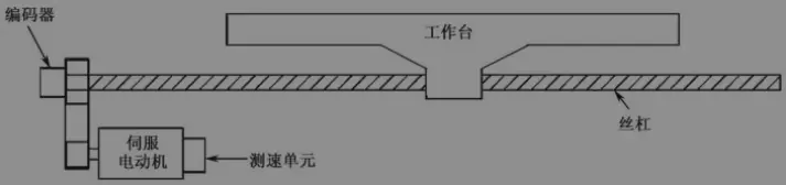
② The servo motor drives the lead - screw to drive the worktable X and Y to move, the speed - measuring unit coaxial with the motor provides speed feedback, the position - detecting grating scale is installed on the worktable plane, and a read/write head is installed on the moving part to read and feedback the actual position of the worktable movement (as shown in the figure below). This control method is also called full - closed - loop control. Its advantage is that it can eliminate the gaps in mechanical transmission, compensate for the manufacturing errors of mechanical transmission parts, and obtain higher positioning accuracy. However, its drawback is that the structure is relatively complex. During operation, the temperature rise of the lead - screw shaft will cause the lead - screw to thermally expand, reducing the positioning accuracy.
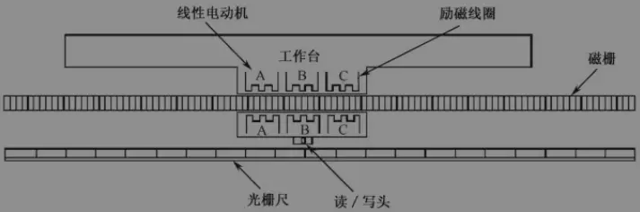
③ The linear motor directly drives, and the position - detecting grating scale provides position feedback (as shown in Figure 2.29). This control method is also full - closed - loop control. Compared with the full - closed - loop servo - motor drive, its advantage is that it uses direct drive, cancels the mechanical intermediate transmission link from the motor to the worktable, has no wear, high - speed response, a relatively simple drive positioning system, and high control accuracy.
(1) Analysis of SMT Mounter Mounting Accuracy Parameters and How to Measure Them