 PCB
PCB FPC
FPC Rigid-Flex
 FR-4
FR-4 HDI PCB
 Rogers High-Frequency Board
 PTFE Teflon High-Frequency Board
 Aluminum
 Copper Core
 PCB Assembly
 LED light PCBA
 Memory PCBA
 Power Supply PCBA
 New Energey PCBA
 Communication PCBA
 Industrial Control PCBA
 Medical Equipment PCBA
 Testing Service
 PCBA Testing Service
 Certification Application
 RoHS Certification Application
 REACH Certification Application
 CE Certification Application
 FCC Certification Application
 CQC Certification Application
 UL Certification Application
 Transformers, Inductors
 High Frequency Transformers
 Low Frequency Transformers
 High Power Transformers
 Conversion Transformers
 Sealed Transformers
 Ring Transformers
 Inductors
 Wires,Cables Customized
 Network Cables
 Power Cords
 Antenna Cables
 Coaxial Cables
 Net Position Indicator
 Solar AIS net position indicator
 Capacitors
 Connectors
 Diodes
 Embedded Processors & Controllers
 Digital Signal Processors (DSP/DSC)
 Microcontrollers (MCU/MPU/SOC)
 Programmable Logic Device(CPLD/FPGA)
 Communication Modules/IoT
 Resistors
 Through Hole Resistors
 Resistor Networks, Arrays
 Potentiometers,Variable Resistors
 Aluminum Case,Porcelain Tube Resistance
 Current Sense Resistors,Shunt Resistors
 Switches
 Transistors
 Power Modules
 Isolated Power Modules
 AC-DC Power Modules
 DC-AC Module(Inverter)
 RF and Wireless
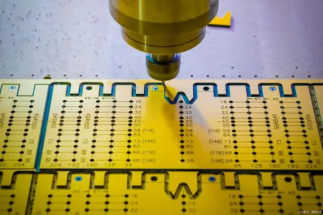
Alignment Accuracy and Pretreatment Steps in the Lamination Process of Multilayer PCBs
Alignment Accuracy and Pretreatment Steps in the Lamination Process of Multilayer PCBs
In the manufacturing of multilayer PCBs, lamination is the process of bonding multiple inner core boards (Cores) and prepreg sheets (Prepregs) into a single unit through high temperature and pressure. Alignment accuracy and pretreatment steps are crucial factors in ensuring the reliability of interlayer electrICal connections and signal integrity.
I. How to Ensure Interlayer Alignment Accuracy?
The alignment accuracy of multilayer PCBs directly affects the positioning of interlayer vias and the reliability of signal transmission. The main technical measures include:
1、Mechanical Locating Holes (Tooling Holes)
Design of Locating Holes: High - precision locating holes (usually 4) are pre - drilled on each core board and prepreg sheet, which match the locating pins of the laminator.
Error Control: The diameter tolerance of the locating holes needs to be controlled within ±0.025 mm to ensure that the deviation when the core boards are stacked is less than 50 μm.
2、Optical Alignment System
Fiducial Mark: Optical alignment marks (such as cross - lines or circular marks) are set on the edge or non - functional area of the core board. The positions of the marks on each layer are captured by a CCD camera.
Automatic Compensation: The laminating equipment adjusts the position of the core board in real - time according to the mark offset, compensating for deviations caused by thermal expansion or mechanical errors.
3、Control of Material Stability
Core Board Pretreatment: The core board is baked before lamination to remove moisture and stress, reducing deformation caused by material expansion at high temperatures.
Selection of Prepreg: Low - flow Prepreg is used to reduce the impact of resin flow on the interlayer position.
4、Optimization of Lamination Process Parameters
Temperature and Pressure Curve: The heating rate and pressure value are controlled in stages to avoid interlayer slippage caused by the too - fast flow of resin.
Vacuum Lamination: Bubbles are removed in a vacuum environment to reduce local stress deformation caused by uneven resin distribution.
II. Impact of Pretreatment Steps (Black Oxidation/Brown Oxidation) on Lamination Quality
Before lamination, the inner - layer copper suRFace needs to undergo chemical treatment (black oxidation or brown oxidation) to enhance the bonding force between the copper layer and the resin and prevent delamination. The specific functions are as follows:
1、Black Oxidation Treatment
Chemical Process: The copper surface is oxidized to form a black copper oxide (CuO) micro - crystal structure, which greatly increases the surface area (roughness).
Functions:
Provides a mechanical anchoring effect, improving the adhesion strength between the resin and copper.
Prevents the formation of voids due to interface separation when the resin cures and shrinks.
Disadvantage: Excessive oxidation may cause the copper layer to become brittle, reducing the reliability of the circuit.
2、Brown Oxidation Treatment
Chemical Process: A brown organometallic complex (such as benzotriazole compounds) is formed to create a uniform passivation layer.
Functions:
Forms an organic film chemically bonded to the copper surface, enhancing resin wettability.
Suitable for high - frequency and high - speed boards (such as PTFE substrates), avoiding the impact of copper oxide on signal loss.
3、Selection between Black Oxidation and Brown Oxidation
Black Oxidation: Suitable for ordinary FR - 4 substrates, with low cost but may introduce high - frequency losses.
Brown Oxidation: Suitable for high - frequency materials (such as Rogers, Isola), more friendly to signal integrity.
4、Consequences of Pretreatment Failure
Risk of Delamination: If the copper surface is not sufficiently roughened or is contaminated, the resin and the copper layer are likely to separate after lamination.
Black Pad Effect: In the ENIG surface treatment, residues from black oxidation may cause poor bonding between the nickel layer and copper, leading to solder joint detachment.
III. Example of a Typical Lamination Process Flow
1、Preparation of Inner - layer Core Boards: Complete pattern etching → black oxidation/brown oxidation treatment → baking for dehumidification.
2、Stacking Structure (Book Building): Stack the core boards, prepregs, and copper foils in sequence and align them through the locating holes.
3、Parameter Settings of the Laminator:
Temperature: 170–190°C (adjusted according to the resin type).
Pressure: 200–400 psi, with staged pressurization.
Time: 60–120 minutes (including heating, pressure - holding, and cooling stages).
4、Post - treatment: Cool to room temperature → remove resin bleed → inspect for delamination and alignment accuracy.
IV. Key Quality Control Indicators
1、Layer - to - Layer Misalignment: The concentricity of the vias and the inner - layer pads is detected by X - ray, and the misalignment should be less than 20% of the via diameter.
2、Resin Filling Degree: Cross - section analysis is used to observe whether the resin completely fills the interlayer voids.
3、Thermal Stress Test: The 288°C solder float test is used to verify the delamination resistance.