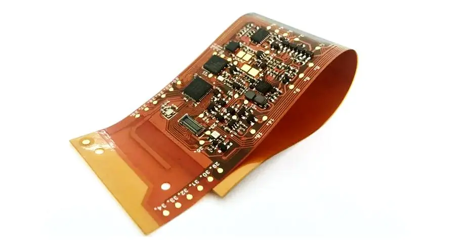
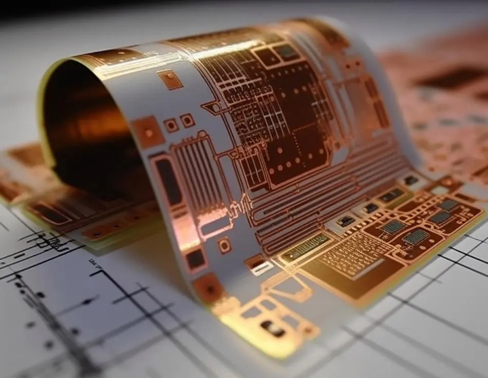
Flexible printed circuits (FPCs) are widely used in electronic devices requiring mechanical flexibility, such as foldable smartphones, wearable devices, and automotive electronics. The routing design in the bending area is a critical factor affecting FPC reliability, as improper wire layout can lead to fatigue fracture under repeated bending. Among various design parameters, the ratio of the wire’s bending radius (R) to its width (W) is a core indicator to avoid wire breakage. This article details the recommended ratio ranges, influencing factors, and practical design considerations.
The bending radius-to-line width ratio (R/W) is defined as the ratio of the inner radius of the bent wire to the wire’s actual width. Industry standards (e.g., IPC-2223) and practical engineering experience provide clear guidelines:
- Static bending (one-time folding or infrequent bending): The R/W ratio should be ≥10:1. For example, a 0.2mm wide wire requires a minimum bending radius of 2mm. This ratio ensures the wire does not experience excessive tensile stress (typically ≤150MPa for copper conductors) during bending, avoiding immediate or latent damage.
- Dynamic bending (repeated folding, ≥10,000 cycles): The ratio needs to be increased to ≥15:1. In applications like foldable phone hinges (up to 100,000 bending cycles), a 0.1mm wide wire should have a bending radius of at least 1.5mm. Higher ratios reduce fatigue accumulation in the copper layer, extending the FPC’s service life.
- Ultra-fine wires (width ≤0.1mm): Due to their smaller cross-sectional area and lower mechanical strength, the R/W ratio should be further increased to ≥20:1. A 0.08mm wide wire, for instance, requires a minimum bending radius of 1.6mm to prevent brittle fracture.
The recommended R/W ratio is not fixed; it varies with FPC material, wire structure, and operating environment:
- Copper layer thickness: Thicker copper (e.g., 35μm) is stiffer and more prone to cracking. For 35μm thick copper wires, the R/W ratio should be 20-30% higher than that for 18μm thick copper (e.g., from 10:1 to 12:1 for static bending).
- Wire orientation: Wires routed parallel to the bending axis (longitudinal routing) have higher stress resistance. For transverse routing (perpendicular to the bending axis), the R/W ratio should be increased by 50% (e.g., from 10:1 to 15:1) to compensate for higher tensile stress on the outer arc.
- Substrate material: Polyimide (PI) substrates have better flexibility than polyester (PET). For PET-based FPCs, the R/W ratio needs to be 10-15% larger than PI-based ones, as PET has lower elongation at break (typically 100-150% vs. 200-300% for PI).
- Operating temperature: High temperatures (≥85℃) reduce copper’s fatigue resistance. In high-temperature environments, the R/W ratio should be increased by 20-30% to counteract the accelerated aging of the conductor and substrate.
In addition to controlling the R/W ratio, the following design practices can further prevent wire breakage in FPC bending areas:
- Avoid sharp corners in the bending path; use smooth arcs with a continuous radius (no abrupt changes in curvature) to distribute stress evenly.
- Reduce wire density in the bending area; maintain a spacing of at least 1.5 times the wire width between adjacent wires to prevent mutual extrusion during bending.
- For dynamic bending applications, use annealed copper (softer than standard electrolytic copper) to improve fatigue resistance, allowing a moderate reduction in the R/W ratio (e.g., from 15:1 to 12:1) while maintaining reliability.
- Apply a protective coating (e.g., acrylic or epoxy) on the bending area to enhance mechanical support, especially for fine-pitch wires with small R/W ratios.
To avoid wire breakage in the bending area of flexible PCBs, the ratio of the wire’s bending radius to its width (R/W) must be strictly controlled. For static bending, a minimum ratio of 10:1 is recommended; for dynamic bending or ultra-fine wires, the ratio should be ≥15:1 or 20:1, respectively. Additionally, factors such as copper thickness, wire orientation, substrate material, and operating temperature need to be considered to adjust the ratio appropriately. By adhering to these guidelines and combining practical design optimizations, the mechanical reliability of FPCs under bending conditions can be significantly improved.
 Capacitors
 Connectors
 Diodes
 Embedded Processors & Controllers
 Communication Modules/IoT
 Resistors
 Switches
 Transistors
 Power Modules
 RF and Wireless
 PCB
PCB FPC
FPC Rigid-Flex
 FR-4
FR-4 HDI PCB
 Rogers High-Frequency Board
 PTFE Teflon High-Frequency Board
 Aluminum
 Copper Core
 PCB Assembly
 LED light PCBA
 Memory PCBA
 Power Supply PCBA
 New Energey PCBA
 Communication PCBA
 Industrial Control PCBA
 Medical Equipment PCBA
 Testing Service
 PCBA Testing Service
 Certification Application
 RoHS Certification Application
 REACH Certification Application
 CE Certification Application
 FCC Certification Application
 CQC Certification Application
 UL Certification Application
 Transformers, Inductors
 High Frequency Transformers
 Low Frequency Transformers
 High Power Transformers
 Conversion Transformers
 Sealed Transformers
 Ring Transformers
 Inductors
 Wires,Cables Customized
 Network Cables
 Power Cords
 Antenna Cables
 Coaxial Cables
 Net Position Indicator
 Solar AIS net position indicator
 Digital Signal Processors (DSP/DSC)
 Microcontrollers (MCU/MPU/SOC)
 Programmable Logic Device(CPLD/FPGA)
 Through Hole Resistors
 Resistor Networks, Arrays
 Potentiometers,Variable Resistors
 Aluminum Case,Porcelain Tube Resistance
 Current Sense Resistors,Shunt Resistors
 Isolated Power Modules
 AC-DC Power Modules
 DC-AC Module(Inverter)